Technical_reference - 第4页
Technical Service Manual 4 Revision Dat e: August 2004 PURPOSE OF THIS M ANUA L & WHO SHOULD USE IT CAUTION IM PROPER SAFETY PRECAUTIONS OR UNSAFE WORK ME THODS MAY RESULT IN SERIOUS INJURY! The following conditions …
Technical Service Manual 3 Revision Date: August 2004
E - ASSOCIATED SUBSYSTEMS _____________________________________________________ 88
TRUE N2 / AIR SWITCHING ------------------------------------------------------------------------------------------------------------------------ 88
BATTERY BACK-UP FOR PC, CONTROLLER, CONVEYOR, AND HOOD LIFTS------------------------------------------------- 89
PRODUCT TRACKING AND ALARM------------------------------------------------------------------------------------------------------------- 89
COMPUTER CONTROLLED EDGE-RAIL LUBRICATION--------------------------------------------------------------------------------- 90
AUTO CHAIN LUBE TANK/PUMP ASSY ------------------------------------------------------------------------------------------------------- 91
BOARD SUPPORT------------------------------------------------------------------------------------------------------------------------------------- 93
CONTROLLED COOLING--------------------------------------------------------------------------------------------------------------------------- 93
CONTROLLED EXHAUST SYSTEM (AIR ONLY OR OVENS EQUIPPED WITH AIR SWITCHING)------------------------- 94
INTEGRATED EXHAUST STACK FILTER------------------------------------------------------------------------------------------------------ 95
FLUX EVACUATION SYSTEM --------------------------------------------------------------------------------------------------------------------- 96
FUNCTION OF THE FLUX EVACUATION SYSTEM----------------------------------------------------------------------------------------- 97
HOODLIFTS---------------------------------------------------------------------------------------------------------------------------------------------- 99
THREE ACTUATOR SYSTEM---------------------------------------------------------------------------------------------------------------------105
INDEPENDENT ALARM SCANNER OVER-TEMP & ALARM/SHUTDOWN---------------------------------------------------------106
INDIVIDUAL CELL SENSING ---------------------------------------------------------------------------------------------------------------------107
HEATER CELL OVER-TEMPERATURE SWITCHES --------------------------------------------------------------------------------------110
LIGHT TOWER-----------------------------------------------------------------------------------------------------------------------------------------111
ON-BOARD OXYGEN (O2) ANALYZER-------------------------------------------------------------------------------------------------------112
POLAR COOL™ OPTION --------------------------------------------------------------------------------------------------------------------------114
EXTERNAL COOLING LIQUID SUPPLY OPTION ------------------------------------------------------------------------------------------119
RAIL ADJUST: -----------------------------------------------------------------------------------------------------------------------------------------121
SMEMA INTERFACE---------------------------------------------------------------------------------------------------------------------------------124
TEMPERATURE PROFILE PLOTTING (PRECISION PROFILING)--------------------------------------------------------------------132
Technical Service Manual 4 Revision Date: August 2004
PURPOSE OF THIS MANUAL & WHO SHOULD USE IT
CAUTION
IMPROPER SAFETY PRECAUTIONS OR UNSAFE WORK METHODS MAY RESULT IN SERIOUS INJURY!
The following conditions may be encountered
when working on any reflow oven:
Þ High Temperature areas (up to 350
o
C)
Þ High Voltage areas (up to 480 VAC)
Þ High Current areas (up to 200 Amps)
Þ Moving Mechanical Parts and Systems
Þ Heavy Components
Þ Sensitive Electronic Components
This manual is intended to meet the needs of service personnel responsible for the regular service of Vitronics-Soltec
Reflow Ovens. Vitronics-Soltec does not consider this manual a specification for Vitronics-Soltec products or any
components contained in those products and reserves the right to change information contained in this manual without
notification. This manual is intended to be a reference. Some of the topics explain manufacturing and assembly
methods and practices; however, many topics deal with specific service information and methods. Hopefully, insight will
be provided about the various sub-systems of the electrical control system to allow quick identification of problems and
possible solutions.
IT IS THE RESPONSIBILITY OF THE END USER TO ENSURE THAT ONLY QUALIFIED PERSONNEL
SHOULD BE ALLOWED TO WORK ON THE EQUIPMENT. THIS MANUAL IS FOR SERVICE OF VITRONICS-
SOLTEC OVENS BY TRAINED QUALIFIED PERSONNEL.
AN APPROPRIATE UNDERSTANDING AND USE OF
SAFETY PROCEDURES WHEN WORKING ON AND AROUND THE OVEN IS NECESSARY
Some people who might use this manual are:
• Vitronics-Soltec service technicians
• Customer service technicians
• Customer facilities maintenance personnel
• Technical operators
Technical Service Manual 5 Revision Date: August 2004
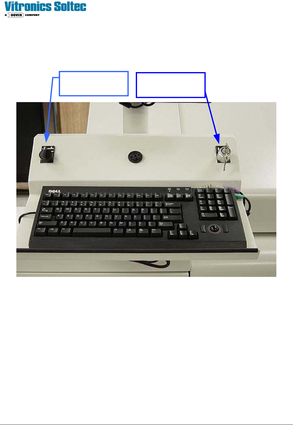
CONTROL PANEL SYMBOLS
XPM
2
OPERATOR CONTROL PANEL
KEY SWITCH RAISES
AND LOWERS THE
OVEN HOOD
SELECTOR SWITCH
ADJUSTS RAIL
IN or OUT