Technical_reference - 第40页
Technical Service Manual 40 Revision Dat e: August 2004 TEST PROCEDURE FOR H EATER GROUND CONT INUIT Y 1) Disc onnect the m ain power connection to the oven and dis able all heater circuit br eaker s. 2) Check each line …
Technical Service Manual 39 Revision Date: August 2004
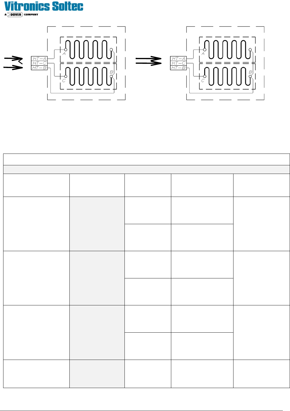
Fig. A Fig. B
(Parallel) (Series)
XPM
2
Release Date: February 25, 2004
Heater Element Resistance Reference Chart
VOLTAGE RESISTANCE HOLE SIZE HEATER ASSY #
(
stamped on face plate)
ELEMENT #
(2 ELEMENTS PER
HEATER)
.136”
3085401
200 - 208 Volts
(LOW RANGE)
Test: 8.55 Ω - 9.45 Ω
9.0 Ω nominal
18.0 Ω = 1 open element
.170”
3160501
0866601
.136”
3085401
380 - 415 Volts
(LOW RANGE)
Test: 34.20 Ω - 37.80 Ω
36.0 Ω nominal
.170”
3160501
0866601
.136”
3085402
220 - 240 Volts
(HIGH RANGE)
Test: 11.40 Ω - 12.60Ω
12.0 Ω nominal
24.0 Ω = 1 open element
.170”
3160502
0904001
440 – 480 Volts
(HIGH RANGE)
Test: 45.60 Ω - 50.40 Ω
48.0 Ω nominal
.136”
3085402
0904001

Technical Service Manual 40 Revision Date: August 2004
TEST PROCEDURE FOR HEATER GROUND CONTINUITY
1) Disconnect the main power connection to the oven and disable all heater circuit breakers.
2) Check each line to the respective heater element for a short to ground using an Ohmmeter.
3) The heater element conductors should be completely isolated from ground (i.e. open circuit with reference to ground).
MAXIMUM HEATERS ON
The Oven Control Program limits the maximum number of heaters to be energized at the same time to seven.
MAXIMUM PHASE IMBALANCE
The difference between the maximum loaded phase and the minimum loaded phase is limited to two heaters by the Oven
Control Program. The Oven Control Program limits the number of heaters “ON” at the same time for each phase.
THERMOCOUPLES
All thermocouples in the oven are type 'K', and identified by a red (-) and a yellow (+) wire. Connectors, wires and
terminals must be designated for use with type “K” thermocouples.
TEST PROCEDURE
1) Remove the thermocouple connection block from the front of the AI board in the Oven controller.
2) Measure the resistance of each thermocouple using an Ohmmeter. (All T/Cs have one side connected to ground.For
best results, isolate the T/C being tested)
3) The resistance of a thermocouple wire should be approximately 5 ohms.
4) Test for shorts between the thermocouple wires by disconnecting the thermocouple cable from the plug on the
outside of the cell.
5) Measure the resistance between the two thermocouple wires; it should be open circuit with the connector removed
from the front of the controller.
6) Check for short circuit to ground on both thermocouple wires.
7) Wiring connections must be tight. Verify that all negative thermocouple connections are grounded, along with all
unused thermocouple ports on the front of the controller.
8) Check to determine that one side of the TC probe is NOT common to ground.
Technical Service Manual 41 Revision Date: August 2004
HEATER PLATE REPLACEMENT
CAUTION:
BEFORE STARTING ANY MAINTENANCE, DISCONNECT THE
OVEN FROM ALL POWER SOURCES.
TOP HEATER REPLACEMENT
1. Locate the defective heater.
2. From inside the tunnel, remove the ICB (inter-cell baffles) from either side of the heater cell.
NOTE: DO NOT REMOVE THE BACK ANGLE BRACKET.
3. Note the location of the thermocouple(s) and circle the hole(s) with a permanent marker. Unscrew the bracket holding
the thermocouple in place and gently straighten the thermocouple.
NOTE: DO NOT USE PLIERS TO STRAIGHTEN THE THERMOCOUPLE(S).
4. Remove the angle bracket (at front of top heater plate) ( at front and back on bottom heater plates)
5. Carefully ease the heater plate away from the cell body to expose the wire connections.
6. The terminal blocks are fragile, CAREFULLY disconnect the wires from these blocks. (Using two wrenches (11/32"
open end wrenches 1/8" thick or less), 1 to hold the nut and 1 to turn the screw- (Air Oven Panels only)
7. Disconnect the ground wire.
8. Install the new heater plate following the removal sequence in reverse. Be sure that the thermocouple(s) goes
through the correct hole in the heater plate.
BOTTOM HEATER REPLACEMENT
1. Locate the defective heater.
2. For edge rail systems: remove the top mounting screws from the rails. Remove the chain from the sprockets and
prop the rails out of the way of the heater plate.
3. For mesh conveyor systems: prop the conveyor out of the way of the heater plate and remove the wear rods.
4. Follow instructions 2 to 8 in the TOP HEATER REPLACEMENT instructions above.
TEST PROCEDURE FOR HEATER CONTROL
NOTE: DISABLE ALL HEATER CIRCUIT BREAKERS BEFORE PROCEEDING WITH THE TESTS IN
THIS SECTION.
Ensure that the screws clamping the PCB to the SSRs are all tight. Do not over-tighten as this strips the thread in the
SSR.
Manually activate the heater outputs within the Oven Control Program. NOTE: This operation may require a password.
Check all SSRs by activating them one at a time, and viewing the respective LED.
If an LED does not light, there could be a cable problem, the LED might be faulty or the AI's driver circuits could be faulty.