Technical_reference - 第49页
Technical Service Manual 49 Revision Dat e: August 2004 HEATER REMOVE AND REPLACE PROCEDURES Make a clear sket ch of the Inter Cell Baff le (ICB) settings fo r all cells. The ICBs w ill be removed and replaced during thi…
Technical Service Manual 48 Revision Date: August 2004
5 INCHES
2.5 INCHES
2.75 IN
6 IN
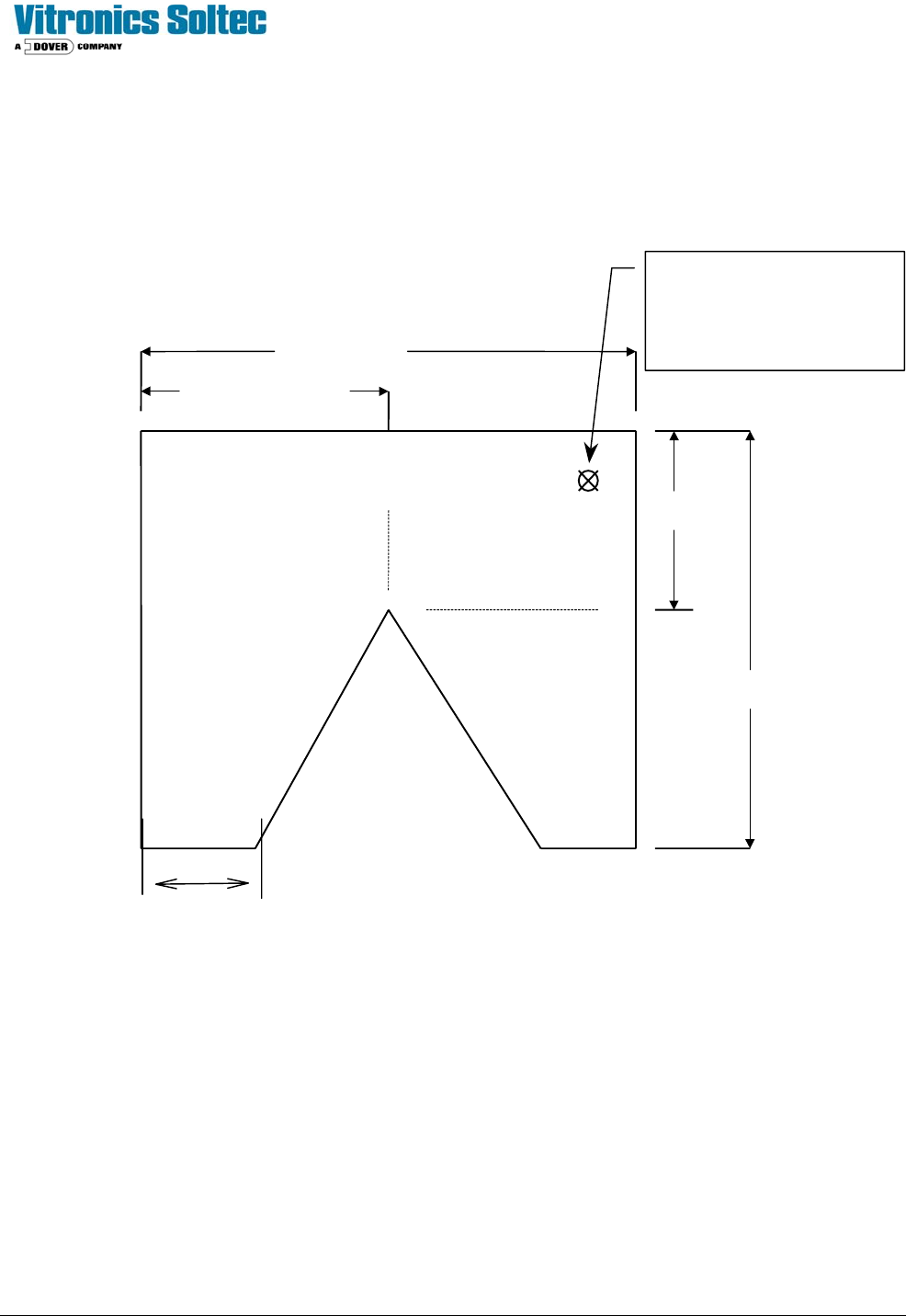
FAN MOTOR GAUGE
-Make from 3/32” alum sheet
3/4 IN
Hole is to facilitate removal of
gauge from under blower
wheel.
¼ inch drill bit, ¼ inch
from out outside edges.

Technical Service Manual 49 Revision Date: August 2004
HEATER REMOVE AND REPLACE PROCEDURES
Make a clear sketch of the Inter Cell Baffle (ICB) settings for all cells. The ICBs will be removed and replaced
during this procedure.
TOP HEATER REMOVAL
1. Remove power from the oven.
2. Loosen the screw holding the thermocouple in place on the cell face. Using a permanent black marker, circle the
thermocouple on the heater face. (This will help relocate the thermocouple when reassembling the cell).
3. Carefully straighten the thermocouple wire and cover it with a piece of 1/8" vinyl tubing.
4. Remove the two Philips head screws holding each ICB in place on the sides of the heater panel. Remove the
ICBs.
5. Remove the two Philips head screws holding the front heater panel bracket. Remove the bracket.
6. Remove the two Philips head screws holding the rear heater panel bracket. Remove the bracket. CAUTION: The
heater panel may drop down.
7. If the heater panel does not drop down by itself, using a hex head wrench, carefully insert the short end into a hole
in the heater panel and gently tug down on the heater panel. Use the 3" putty knife to push the insulation guard
clear of the heater panel.
8. Lower the heater panel enough to gain access to the heater wires on the inside of the cell. Block the panel up with
a 10" 4x4 block of wood to relieve the strain on the wires.
9. Document the wire placement on the connections on the heater panel. They will need to be replaced later in the
same positions.
IT IS VERY IMPORTANT TO USE TWO WRENCHES AND HOLD THE BOTTOM NUT STEADY BECAUSE THE
HEATER FOIL IS DIRECTLY ATTACHED TO THE STUD AT THIS LOCATION. THE CERAMIC BLOCKS ARE
FRAGILE AND EASILY BROKEN. IF THE HEATER FOIL TEARS, IT CANNOT BE REPAIRED AND THE HEATER
PANEL ASSEMBLY MUST BE REPLACED.
10. Remove the four wires by using two 11/32" wrenches. Use one to hold the bottom nut (closest to the panel)
steady while the other unscrews the top nut to free the wire.
11. Disconnect the two wires on the thermal switch.
12. Remove the heater panel and set it aside.

Technical Service Manual 50 Revision Date: August 2004
TOP HEATER REPLACEMENT
1. Retrieve the heater panel for this cell and set the rear of the heater panel into place in the cell between the bracket
and the cell. Be careful not to bend the thermocouple wire. Prop the heater panel up from the front so the heater
wires can be reconnected.
2. Reconnect the wires to the panel referring to the SKETCH made when the panel and wires were removed. Use
two 11/32" wrenches so as NOT break the ceramic block or tear the foil connected to the lower (closest to the
panel) nut on the stud. Do not forget to connect the thermal switch wires.
3. Carefully place the thermocouple wire in its protective 1/8" vinyl tubing through the correct hole in the panel. If you
did NOT circle the thermocouple(s) before removing the panel, then count four rows from the left and six holes
from the front to locate the correct hole.
4. Once the thermocouple is located in its proper hole, raise the heater panel into place.
5. Replace the front panel bracket and fasten it with two Philips head screws. Remove the vinyl tubing protecting the
thermocouple.
6. Replace the left and right ICBs and fasten them in place with two Philips head screws each. Refer to the sketch of
ICB placement to locate and adjust them.
7. Carefully bend the thermocouples into the correct places and replace the clamps and screws. Tighten the screws
.