Technical_reference - 第55页
Technical Service Manual 55 Revision Dat e: August 2004 PRINTED CIRCUIT BOA RD DESIGN CONSIDERATIONS Printed circuit board ( PCB) design is an im por tant factor in the selection of the oven conveyor sy stem . T he mes h…
Technical Service Manual 54 Revision Date: August 2004
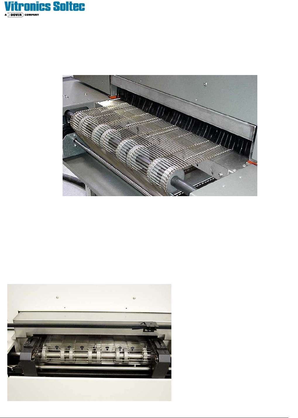
MESH BELT CONVEYOR SYSTEM
The mesh belt conveyor system is used to process single sided surface mount printed circuit boards.
Mesh Belt Conveyor
COMBINATION CONVEYOR SYSTEM
The combination belt/rail conveyor has both the edge rail and the mesh belt. The mesh belt is below the edge rail
conveyors, and both conveyors are driven together. The belt conveyor is shorter than the outside edge of the machine
with the sheet metal covers on, and shorter than the end of the rails with chain guards installed.
A
pproximately 3 inches between end of
belt and end of rail conveyor (both
ends).
Technical Service Manual 55 Revision Date: August 2004
PRINTED CIRCUIT BOARD DESIGN CONSIDERATIONS
Printed circuit board (PCB) design is an important factor in the selection of the oven conveyor system. The mesh
belt conveyor system limits PCB processing to single sided PCBs without projecting leads or traces on the bottom of the
PCB. The edge/rail conveyor system allows double-sided PCBs to be processed with few restrictions. Major factors to
be considered in processing PCBs on the edge/rail conveyor system are described below.
PCBs processed on the edge/rail conveyor system are supported by pins projecting from the chains on each side of the
PCB. These pins can act as heat sinks drawing heat away from the PCB. This heat sink effect can result in uneven
heating of the PCB if the artwork (circuit traces, contact pads, etc.) contacts the pins supporting the PCB. To avoid
uneven heating problems, allow at least 0.20 inches (5mm) of clearance from the artwork to the edge of the PCB resting
on the pins.
The rail can be adjusted for different PCB widths. However, there are limits to the rail width adjustment. Minimum PCB
width is 2.0 inches (50.8 mm) and the maximum is 18 inches (450mm). For wide tunnel conveyors the maximum width is
22 inches.
The edge/rail conveyor is positioned at the factory to allow the minimum (2.0 inches) and maximum (18 inches) PCB
widths to be processed without moving the fixed rail.
Moving the fixed rail is not recommended unless it is necessary to accommodate other equipment in the production line.
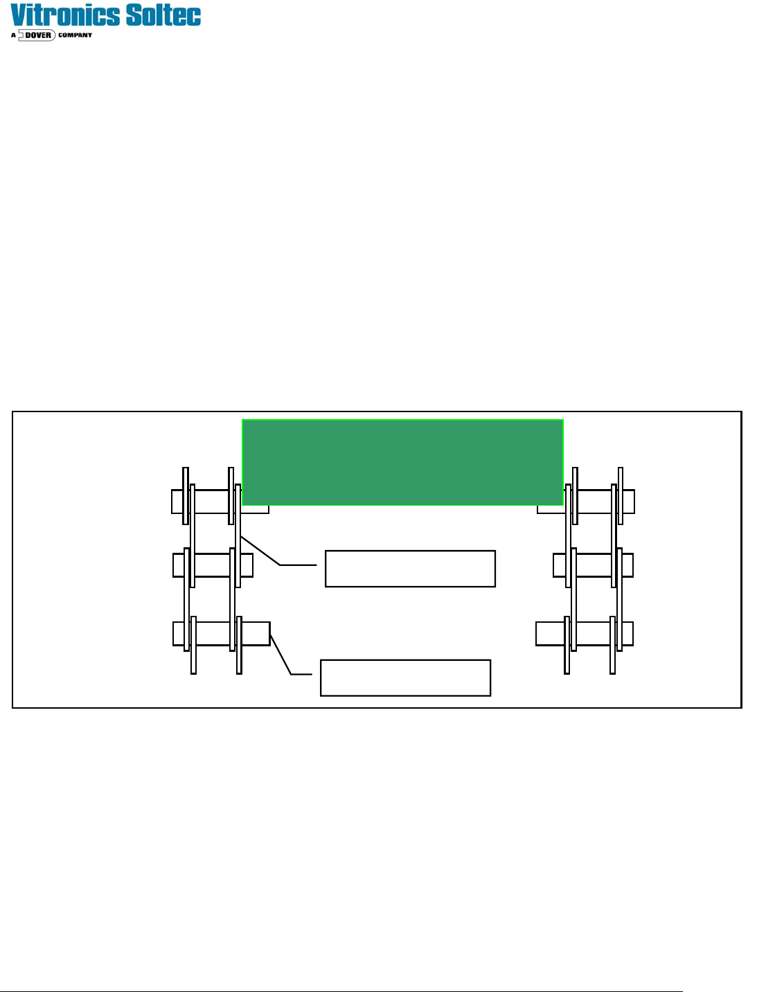
PCB
Extended Pins
Chain Links
Rail Width Measurement Illustration

Technical Service Manual 56 Revision Date: August 2004
PROBLEMS AND POSSIBLE SOLUTIONS (The most likely cause is listed first)
CONVEYOR PROBLEMS
CONVEYOR WILL NOT RUN.
1. Conveyor drive clutch needs adjustment See: 12
2. Check the on/off/stop circuit (Emergency Stops) See: 2
3. K37 & K38
do not operate See: 4
4. Conveyor has no power See: 3
5. I/O relay has failed or is off See: 6
6. Controller to I/O board signal problem See: 8
7. No signal to DC drive module from I/O Board See: 9
8. Unreliable output from the DC drive module See: 7
9. Conveyor motor does not operate See: 11
10. The conveyor is jammed See: 10
11. ( Reserved for future use )
CONVEYOR STOPS RUNNING.
1. There is a board jammed on the conveyor See: 10
2. There is a conveyor jam See: 10
3. The drive clutch needs adjustment See: 12
4. There is an AC circuit failure See: 13
5. An alarm condition has occurred See: 14
6. The E-stop circuit is causing the stop See: 2
7. Unreliable output from the DC drive module See: 7
8. The conveyor motor has stopped running See:11
9. The controller has had a failure. See: 15
CONVEYOR SPEED IS UNSTABLE.
1. Check the conveyor drive clutch See: 12
2. Check the encoder See: 20
3. Check the drive chain tension See: 21
4. Check sprocket shaft alignment See: 18
5. Check the transfer gear assembly See: 16
6. Check the voltage to the encoder See: 22
7. Check the controller See: 15
8. Unreliable output from the DC drive module See: 7
9. Check the Conveyor motor See: 11
10. Check the encoder drive linkage See: 19
11. Chain may need lubrication See: 10