Technical_reference - 第73页
Technical Service Manual 73 Revision Dat e: August 2004 5. CALIBRATION PROCEDURE FOR MINARIK CONT ROLS Tools required: Multimeter (auto-ranging) Sm all non-m etallic sc rewdriver Speed indicator Before connecting the pow…

Technical Service Manual 72 Revision Date: August 2004
B. Conveyor speed can be calibrated to specific requirements. This takes practice, but can yield greater
speed accuracy.
C. The conveyor speed should be measured with a stopwatch every sixty days.
D. Motor brushes wear out.
E. Calibration values may change with the age of the system.
F. Always record the adjusting potentiometer settings before replacing or calibrating a DC drive.
G. When replacing a DC drive, record the potentiometer settings; draw a sketch of the wire hookups; make
sure all wires have labels.
Technical Service Manual 73 Revision Date: August 2004
5. CALIBRATION PROCEDURE FOR MINARIK CONTROLS
Tools required:
Multimeter (auto-ranging)
Small non-metallic screwdriver
Speed indicator
Before connecting the power supply:
1. Set the two ‘Jumper’ to ‘signal’.
2. Set the MAX SPEED pot to full clockwise.
3. Set the MIN SPEED pot to full counter clockwise.
4. Set the IR COMP pot to the setting shown below.
5. Set the TORQUE pot to the setting shown below.
6. Set the signal Pot to full clockwise
With the power supply connected:
1. Set the multimeter to VOLTS AC and measure the input voltage to the control. If the voltage is less than
108V or greater than 132V disconnect the power supply and correct the supply voltage problem.
2. Disconnect the multimeter and set to measure VOLTS DC. Attach leads to the motor side of the control.
- In the Program Diagnostics, set the conveyor speed to 0%.
- Set the MIN speed pot so the conveyor is just barely moving.
3. Set the speed indicator on the front panel to 100 or full speed.
4. Adjust the MAX SPEED pot until the VOLTS DC equals the armature voltage listed on the motor
nameplate.
5. Check the speed of the conveyor.
6. Calibration is complete.
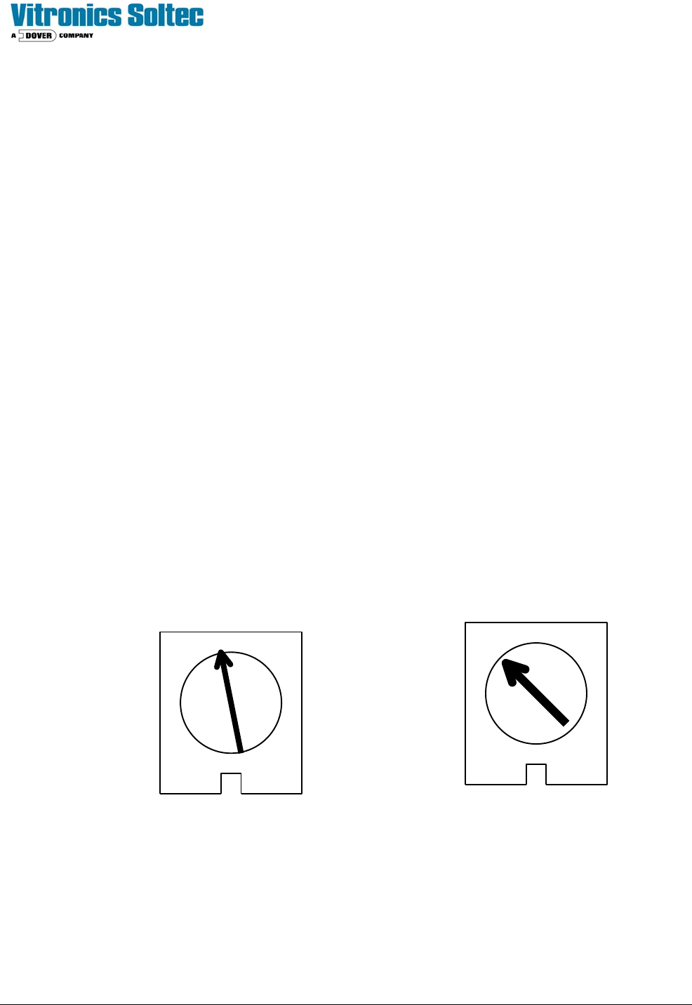
TORQUE IR COMP
MINARIK DRIVE POTENTIOMETER SETTINGS

Technical Service Manual 74 Revision Date: August 2004
REMOVE AND REPLACE CONVEYOR RAILS AND CHAINS
DISCONNECTING RAILS AND CHAINS
1. At the off-load end of the oven, remove the chain guard from each chain by removing the 1/8" hex key head screws.
2. Run the conveyor until the master link for one or both chains comes up just under the rail. Remove the master link(s)
from the chain(s). Unthread the chain from all of the pulleys that it wraps around on its way under the oven. Make sure
that the chain is off the drive sprocket and tie wrap it to the idler shaft just below the end of the oven. Be sure to note the
position of the chain around all pulleys. Go to the on-load end of the oven and remove the chain guards. Pull the chains
out of the rails in the direction of the on-load end of the oven. Let the chains drop down and tie wrap them to the idler
shaft below the end of the oven.
3. If only one master link came into position, run the conveyor until the second chain master link shows up. When it
does, remove it as you did on the other chain.
4. Remove the 5/32" hex head screws holding each rail onto the conveyor assemblies.
5. Remove the rails. DO NOT to let them bend or they may be permanently deformed.
RECONNECTING RAILS AND CHAINS
1. Reconnect each rail to its end assembly using the 5/32" hex head screw.
3. Install the chains in the rails making sure the long pins face in toward the center of the oven. Be careful not to twist
the chains.
4. Slide the chains through the rails until they reach the off-load end of the oven.
5. Rethread the chains on the sprockets and idler pulleys at the on-load end of the oven. Reinstall the chain guards with
the 1/8" hex key head screws.
6. At the off-load end of the Oven, rethread the chains through the sprockets and idler pulleys. Reconnect the master
links in both chains. Make sure the closed end of the keeper clip is facing the direction of conveyor travel (off-load end).
Reinstall the chain guards on the rails with the 1/8" hex key head screws.
7. Make sure the chains are not hung up or twisted anywhere on top or underneath the Oven.