Technical_reference - 第76页
Technical Service Manual 76 Revision Dat e: August 2004 2. Do the “conveyor calibration” desc ribed in the Oven Oper ation Program Manual after the clutch ass em bly is properly adjusted. CONVEYOR DRIVE SYSTEM The c ontr…
Technical Service Manual 75 Revision Date: August 2004
DRIVE MOTOR SERVICE & REPLACEMENT
CONVEYOR DRIVE MOTOR REPLACEMENT
MOTOR LOCATION
There are only two locations for the conveyor motor on all Vitronics-Soltec Reflow Ovens. On an oven with a left to
right conveyor, the motor assembly is in the front right corner of the oven. On an oven with a right to left conveyor
system, the motor assembly is on the front left corner of the oven.
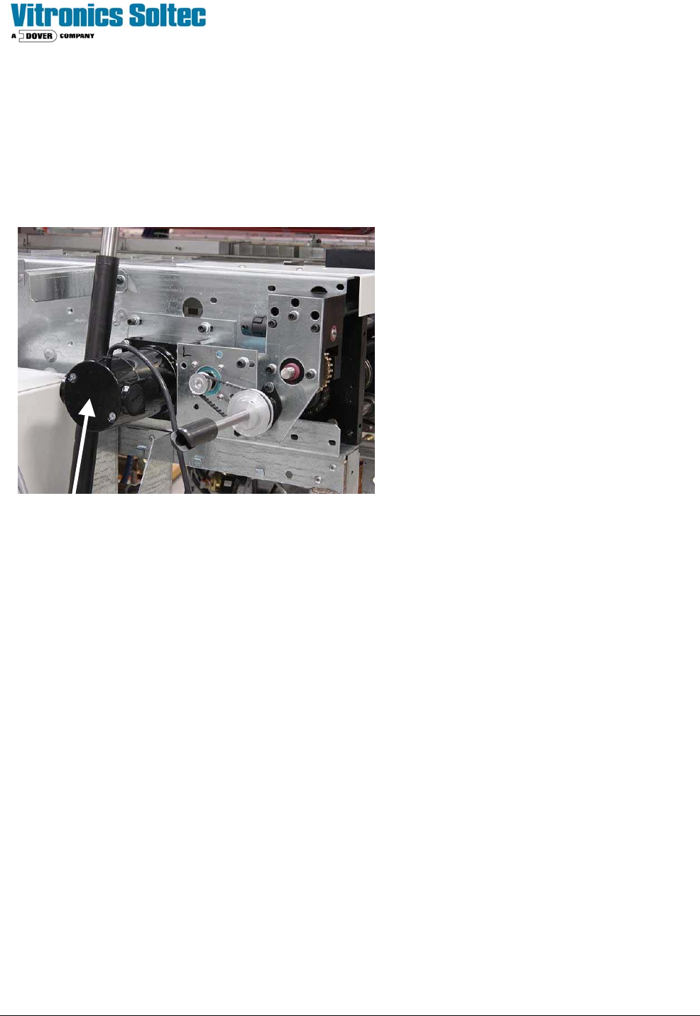
CONVEYOR MOTOR
To remove/replace the Conveyor Drive Motor:
1. Open the Hood
2. Turn off the U.P.S. and disconnect all power from the oven.
3. Remove the long sheet metal piece around the Operator’s Control Panel on the end the oven.
4. The Motor is mounted with four bolts on the Oven Frame “C” Channel. Loosening the four bolts will allow the
Chain to be removed from the Clutch Drive Sprocket without removing the Master Link from the Chain.
5. Unplug the Motor power leads.
6. While supporting the Motor, remove the four bolts. Remove the motor, mounting plate and clutch sprockets from
the Oven.
7. Rotate the Motor to permit access to the setscrews that secure the Clutch Assembly to the Motor Drive Shaft.
Loosen the setscrews and remove the Clutch Assembly, then remove the Motor from the mounting plate.
8. Reverse steps 7 through 1 to replace the Conveyor Drive Motor
THE “MOTOR REPLACEMENT” IS NOT COMPLETE UNTIL YOU:
Check the tension of the Drive Chain as well as the alignment between the Clutch Drive Sprocket and the End Assembly
Drive Sprocket. The chain should have some slack, but not enough to remove the chain from the sprocket(s).
The alignment of the two (2) sprockets should be as exact as possible.
1. Run the oven to verify that the MIN/MAX speed settings with the new motor are similar to the speed settings with the
old motor.
Left To Right Conveyor
Technical Service Manual 76 Revision Date: August 2004
2. Do the “conveyor calibration” described in the Oven Operation Program Manual after the clutch assembly is properly
adjusted.
CONVEYOR DRIVE SYSTEM
The controller supplies an analog signal corresponding to the desired conveyor speed. The DC drive card sends an
amplified signal to the conveyor drive motor.
(The motor has a slip clutch connected to the conveyor shaft that drives the encoder.)
The encoder generates +5 VDC pulses as the motor drive system operates. The pulses go to the controller, which
modifies the analog signal to the DC drive card to compensate for any conveyor speed.
Set up the Conveyor Drive within the Oven Operation Program.
NOTE: This operation may require a password.
If the conveyor motor does not turn, check the following:
1 - Determine that K37 & K38 are energized
2 - Check for 120 VAC at the DC drive board (between terminals L1 and L2). If there is no 120VAC there, make sure that
A1-K12 is energized at the I/O board. Next, check the signal to the DC drive board. The signal should be +10 VDC
between DC drive terminals + and – signal input. If there is no signal at those terminals, make sure the oven
controller card cage is receiving +/– 15 VDC. If the cage is receiving +/– 15 VDC, but the drive is not receiving +10
VDC, there is either a wiring error or the DI board is faulty, or a poor wire connection.
3 - After all electrical signals are present and correct, adjust the IR COMP potentiometer to it's mid-point and adjust the
SIGNAL ADJUST potentiometer on the DC drive board to a level which produces a +90 VDC armature voltage
while under manual computer control. The armature voltage is measured between terminals A1 and A2 on the DC
drive board using a DC Voltmeter.
4 - At this point the MIN SPEED potentiometer should be adjusted to generate an armature voltage of approximately +12
VDC between terminals A1 and A2. This should keep the conveyor running slowly at a 0 VDC signal level.
5 - After the conveyor system has been tested, run the conveyor calibration routine in the Oven Control Program.
The conveyor system should be adjusted for the following speeds:
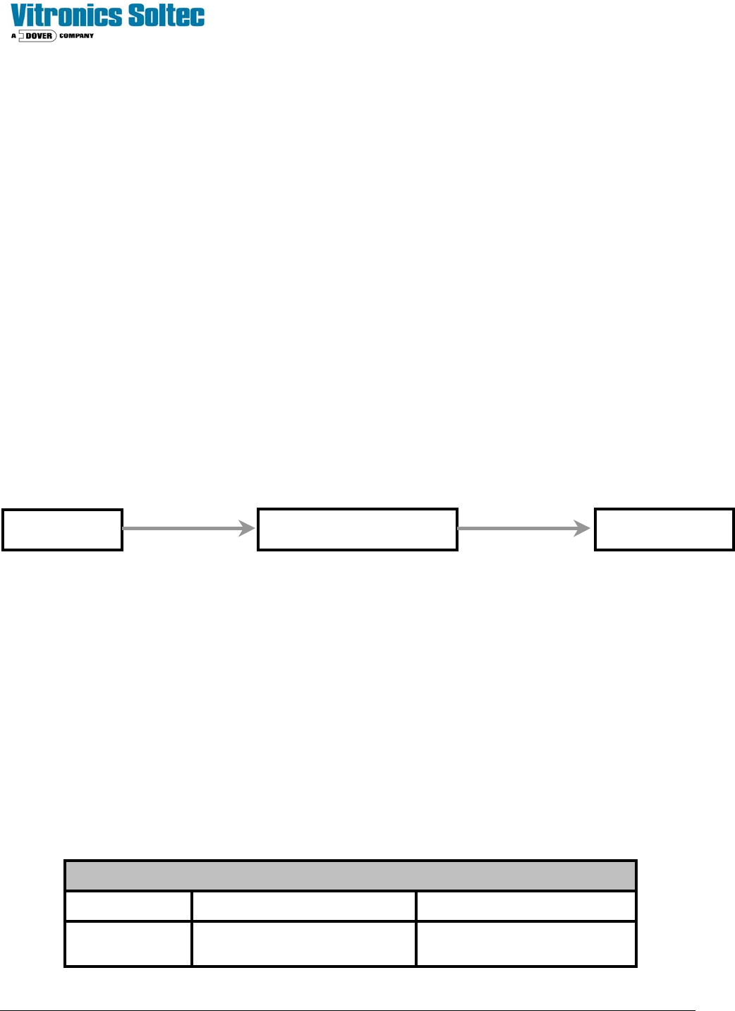
Conveyor Speed Table
MOTOR TYPE MINIMUM SPEED MAXIMUM SPEED
Analog Drive
motor
10.0 inch/min
( 25.4 cm/min)
75.0 inch/min
(178 - 203 cm/min)
MIOP
Oven I/O Board DC Drive
Ribbon Cable Round Cable
Technical Service Manual 77 Revision Date: August 2004
Stepper Drive
motor
0.8 inch/min
( 2.0 cm/min)
45.0 inch/min
(114.3 cm/min)
If the conveyor speed is not consistent after running the conveyor calibration routine, adjust the IR COMP potentiometer
of the conveyor drive up or down to compensate for the fluctuations.
ENCODER SERVICE & REPLACEMENT
Test procedure for encoder signal
To verify that the controller is receiving conveyor encoder pulses, run the conveyor at maximum speed. Monitor the
variable conveyor pulses. This should indicate the number of pulses received by the controller during the last scan
interval.
If the controller is not receiving pulses from the encoder, ensure that the encoder is receiving +5VDC (red wire at
encoder,) and that the wiring is correct. If all is correct, but the conveyor is still not functioning, next: monitor the encoder
pulses using an oscilloscope (wire #1016). If encoder pulses are present, the connection at the front of the DI board
could be faulty or the DI board could be faulty. Use of an oscilloscope should show a ‘square wave’.
A quick check to test for pulses from the encoder is to connect a DC Voltmeter between wires 1007 and 1016 and run the
conveyor. If a voltage level of approximately +1.2 VDC is measured, then pulses are probably being generated. A
voltage level of +5 VDC or 0 VDC indicate a possible fault with the encoder.
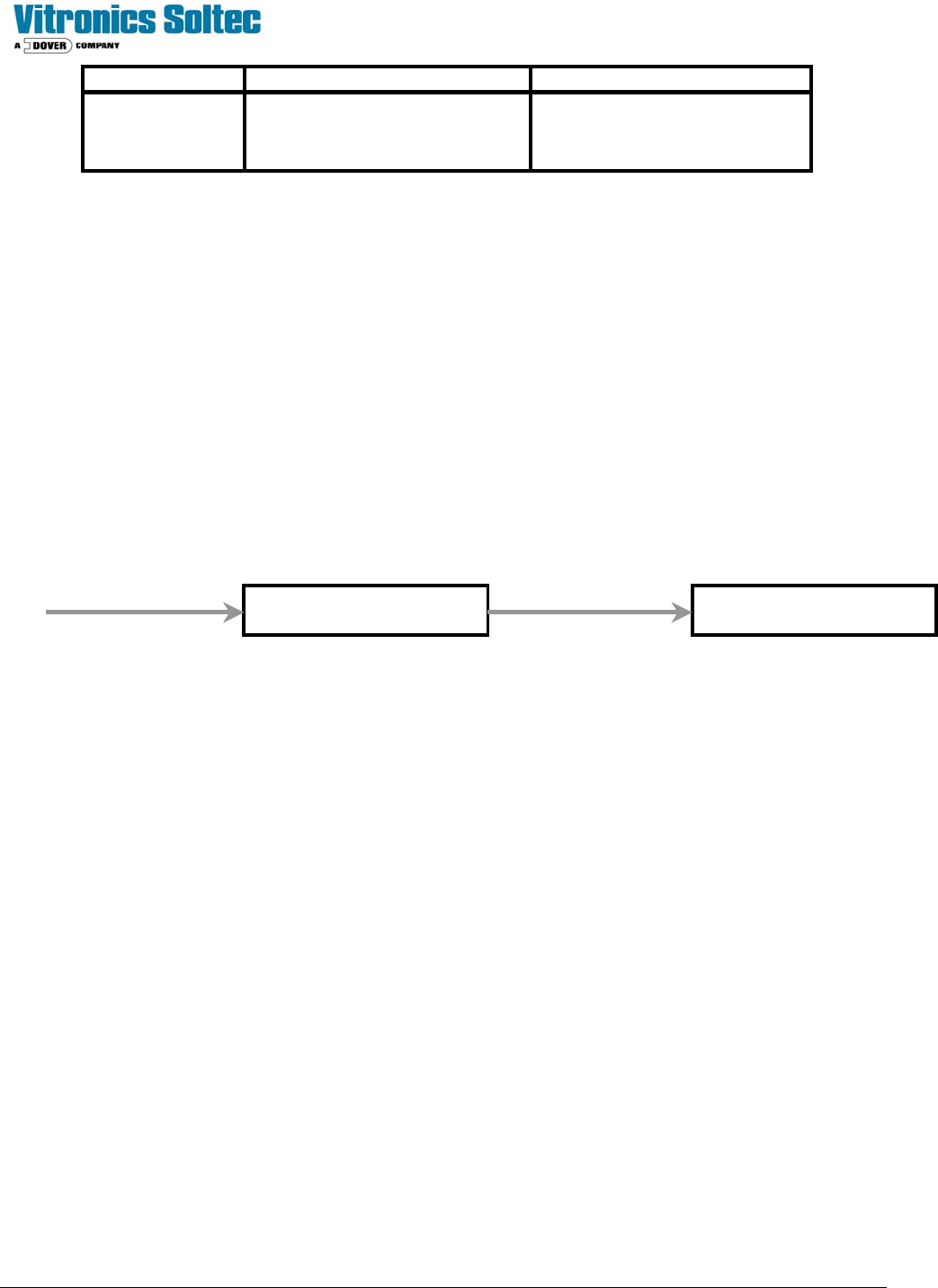
Oven I/O Board
Ribbon Cable
Oven I/O Board
1016 PX9-3 PX2-8 J4-6
TB1-15 Test Point