Technical_reference - 第82页
Technical Service Manual 82 Revision Dat e: August 2004 OVEN CONTROLLER The Vitronic s Control System is com prised of one DI (Digital Input /Output) board, a back -plane board, and one or m or e AI (Analog Input) boards…

Technical Service Manual 81 Revision Date: August 2004
Test procedure for AC Convenience Outlets
Þ Disconnect power to the system. Using an Ohmmeter on its lowest scale, measure the resistance between the
ground terminal on the socket and the ground block on the main electrical back panel. This value should typically be
less than 1 ohm.
Þ With power applied to the system, use a Voltmeter set on the proper scale, measure the voltage between the live and
neutral terminals on the socket, this value should be to either 120 VAC.
D.C. POWER SUPPLY
Two DC Power Supplies provide the controller and various transducers with the required DC voltage. These supplies
are configured for 120 VAC input.
For Power Supply Wiring Connections, refer to the Oven Schematics
Minimum load:
A minimum load is required by the +5 VDC output to maintain proper operation of the other outputs. A load pulling
0.6 Amp is required. If the load is insufficient, a 10 ohm (5 Watt) resistor should be connected between the +5 VDC
output (wire number 1001) and the DC ground output (wire number 1007).
Test procedure for D.C. power supply voltage:
Verify that all single pole circuit breakers on the secondary side of the transformer are off except F52 & F55. Apply
oven power. If 120 VAC is present, measure the output voltages of the DC power supply.
D.C. power supply voltage adjustment:
Adjustments should be made to correct the voltage at the power supply output terminals. Voltage drops occurring
over lengths of cable should have larger cables installed to reduce voltage losses.
Voltage Checks
When troubleshooting an electrical or electronic problem, always verify the basic AC and DC voltages
supplied for operation.
Technical Service Manual 82 Revision Date: August 2004
OVEN CONTROLLER
The Vitronics Control System is comprised of one DI (Digital Input /Output) board, a back-plane board, and one or more
AI (Analog Input) boards. One AI board controls up to 32 process loops. Each additional AI board increases the number
of control loops by 32. The Vitronics Control System controls the temperature of the cells, drives the conveyor and rail
drive motors, and drives various logic signals through the I/O board.
The Vitronics Control System receives all of its instructions from the computer by a serial interface.
NOTE: DI OR AI BOARDS SHOULD NEVER BE INSERTED OR REMOVED WITH POWER APPLIED TO THE
VITRONICS CONTROL SYSTEM!
Test procedure for D.C. input voltage:
The power requirements for the Vitronics Control System, with one AI board, is:
+5.0 - +5.07 VDC @ 2 Amps max
+15 VDC @ 0.1 Amps max (+12 to +15 VDC)
-15 VDC @ 0.1 Amps max (+15 to -15 VDC)
ð Shut off circuit breaker F55 supplying 120 VAC power to DC power supply.
ð Remove DI and AI boards from Vitronics Control System.
Þ Reactivate 120 VAC power to DC power supply. Using a DC Voltmeter, measure the DC voltages at the backplane
connector:
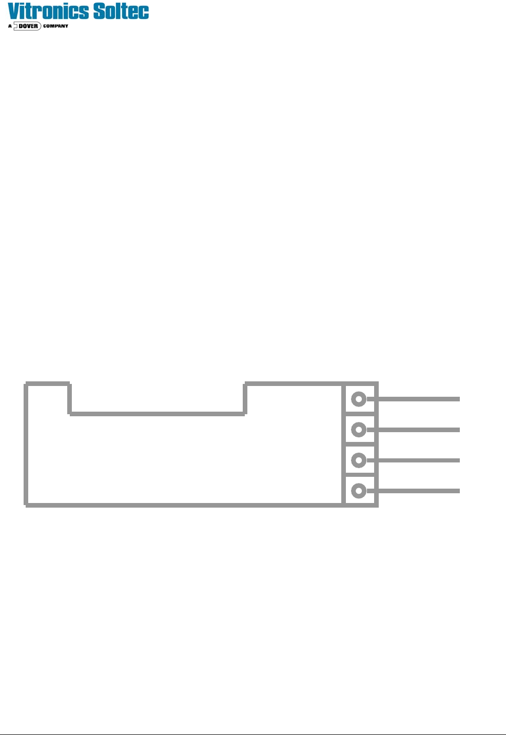
Oven Controller
Circuit Board
Common
+5V
-15V
+15V
1007
1001
1002
1003
Technical Service Manual 83 Revision Date: August 2004
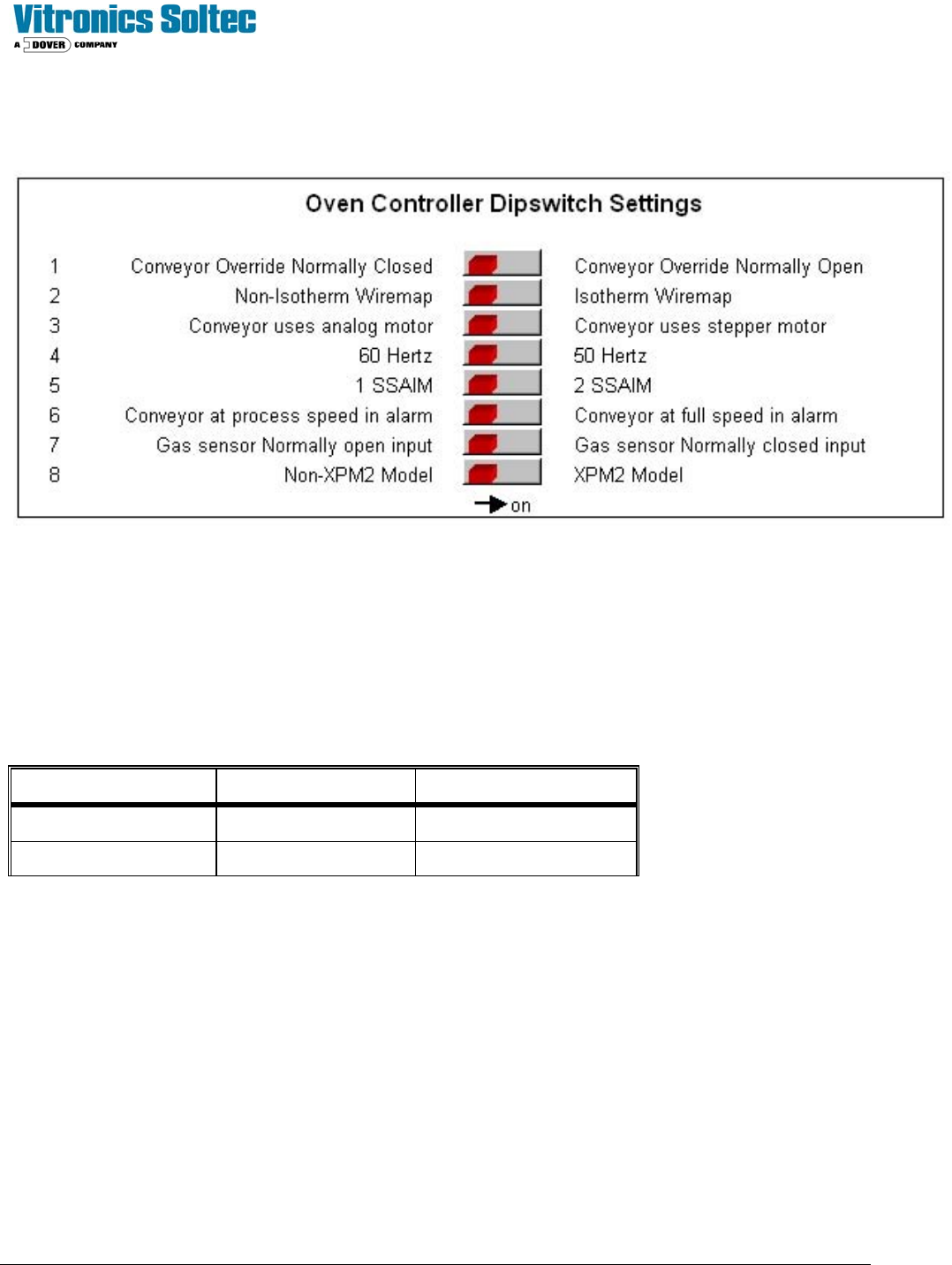
ADDRESSING DIP SWITCHES ON DI BOARD
The following shows the DI board DIP switches and meanings:
The status of the switches can be viewed in the Oven Control Program by selecting “DEBUG”, then “I/O”, then Anafaze
Dipswitch Setting.
(It is not necessary to physically remove the electrical enclosure doors and actually view the actual switches on the Oven
Controller)
ADDRESSING LINKS ON AI BOARD
The AI board contains two series of jumpers, combinations of which dictate the address of the AI board. The following
table identifies the required jumper settings for the first two AI boards in a system:
Board number Channels Jumpers set
1 1 to 32 JU1 and JU11
2 33 to 64 JU2 and JU10
CONTROLLER STATUS
Upon power up the AI board's status lights should be in the following states:
Þ Green light: On, steady.
Þ Orange light: On, flashing at approximately once per second.
Þ If the status lights are not in the above states check the +5 VDC at the terminal block mounted on the motherboard.
If the voltage at this point reads less than +5.00 VDC, check that the minimum load of the power supply is sufficient.
If minimum load conditions are being met, then adjustment of the power supply output voltage may be attempted.
If no problems are detected with the power supply, then replace the EPROM on the DI board.
NOTE: WHEN REPLACING AN EPROM WEAR A STATIC GUARD WRIST STRAP (GROUNDED APPROPRIATELY)
AND USE AN EXTRACTION / INSERTION TOOL TO REMOVE AND REPLACE THE EPROM. ENSURE THAT THE