Technical_reference - 第84页
Technical Service Manual 84 Revision Dat e: August 2004 EPROM IS CORRECT LY ORIENT ED. If the status lights are s till not in the correc t state then replac e the controller boar ds, one at a tim e, in the following ord …
Technical Service Manual 83 Revision Date: August 2004
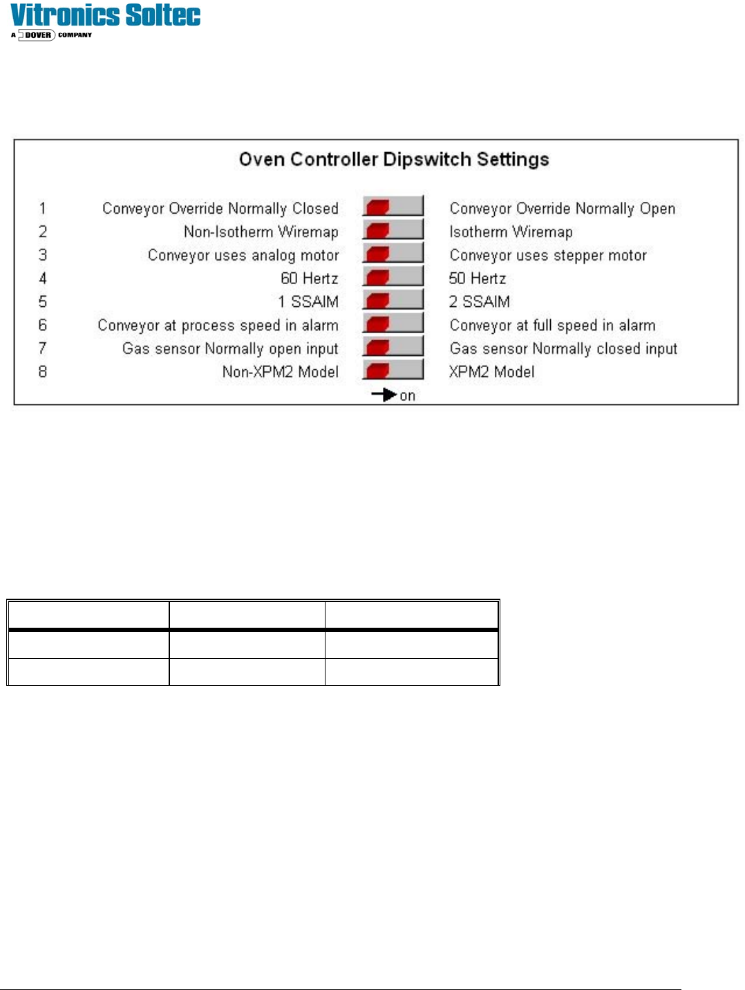
ADDRESSING DIP SWITCHES ON DI BOARD
The following shows the DI board DIP switches and meanings:
The status of the switches can be viewed in the Oven Control Program by selecting “DEBUG”, then “I/O”, then Anafaze
Dipswitch Setting.
(It is not necessary to physically remove the electrical enclosure doors and actually view the actual switches on the Oven
Controller)
ADDRESSING LINKS ON AI BOARD
The AI board contains two series of jumpers, combinations of which dictate the address of the AI board. The following
table identifies the required jumper settings for the first two AI boards in a system:
Board number Channels Jumpers set
1 1 to 32 JU1 and JU11
2 33 to 64 JU2 and JU10
CONTROLLER STATUS
Upon power up the AI board's status lights should be in the following states:
Þ Green light: On, steady.
Þ Orange light: On, flashing at approximately once per second.
Þ If the status lights are not in the above states check the +5 VDC at the terminal block mounted on the motherboard.
If the voltage at this point reads less than +5.00 VDC, check that the minimum load of the power supply is sufficient.
If minimum load conditions are being met, then adjustment of the power supply output voltage may be attempted.
If no problems are detected with the power supply, then replace the EPROM on the DI board.
NOTE: WHEN REPLACING AN EPROM WEAR A STATIC GUARD WRIST STRAP (GROUNDED APPROPRIATELY)
AND USE AN EXTRACTION / INSERTION TOOL TO REMOVE AND REPLACE THE EPROM. ENSURE THAT THE

Technical Service Manual 84 Revision Date: August 2004
EPROM IS CORRECTLY ORIENTED.
If the status lights are still not in the correct state then replace the controller boards, one at a time, in the following order:
AI, DI, Mother board.
RS-232 SERIAL COMMUNICATION CHECK
Make sure the connections on the Oven controller are correct. Check that jumper E20 on the DI board is in place.
Using an Ohm meter check the continuity of the communications cable. The pin assignments should be as follows:
• DB-9 Pin #2 (RX of computer) to I/O Board PX11-17 (TX of VCS)
• DB-9 Pin #3 (TX of computer) to I/O Board PX11-18 (RX of VCS)
• DB-9 Pin #5 (SG) to I/O Board PX11-19 (SG)
The direction of communication failure may be determined by connecting an LED and 470 ohm resistor in series between
PX11-17 and PX11-19 on the Oven I/O board, and a similar LED and resistor network between PX11-18 and PX11-19 on
the Oven I/O board. If both LED's flash and there is no communications, and the computer is not receiving any data, this
could indicate a fault with the cable or the computer serial port. If the LED connected to PX11-18 flashes, then data is
being transmitted to the controller, but the controller is not responding. This could indicate a faulty DI board, EPROM in
the controller, or possibly, the TX and RX cables are reversed. If neither LED flashes then the computer is not
transmitting any data. This could indicate a fault with the cable or the computer serial port (check that the
communications cable is connected into the correct serial port (COM1) on the computer).
A further test is to use an oscilloscope to look at the voltages at PX11-17 (TX) and PX11-18 (RX). The signal should
switch between a positive value (+12 VDC to +16 VDC) and a negative value (-12 VDC to -16 VDC). The signal should
be free from noise greater than +/- 0.2 VDC.
Noisy communication lines can be corrected by grounding the shield of the communication line, as well as moving the
communication link away from any high voltage sources (especially running parallel to the communications lines).
Technical Service Manual 85 Revision Date: August 2004
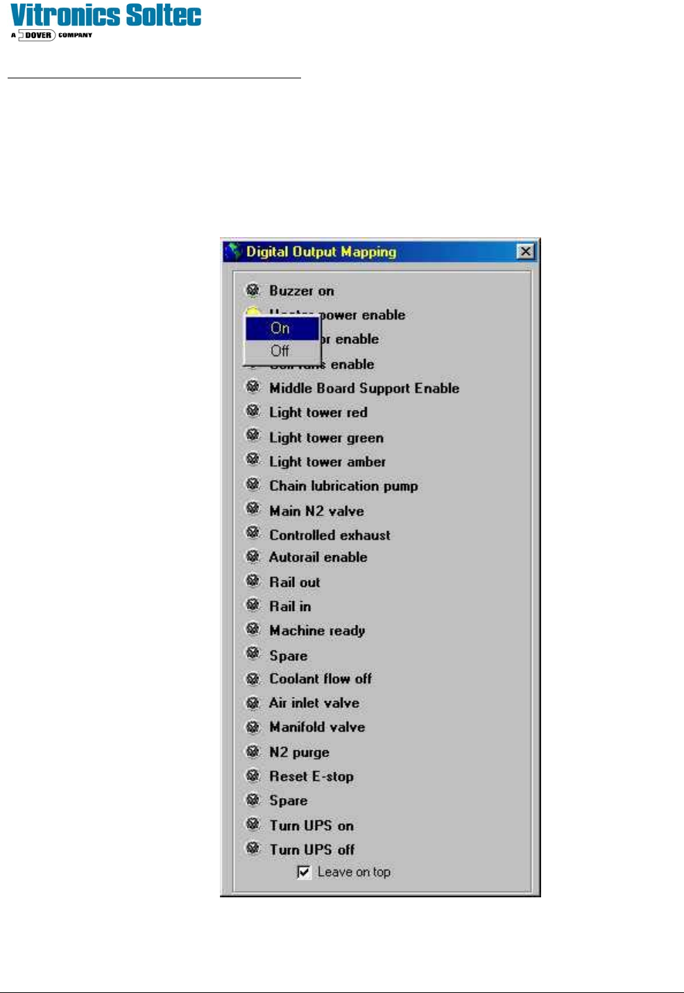
CONTROLLER OUTPUTS (Input/Output board)
The Input/Output board provides the ability to switch 120 VAC power through interposing relays. The Oven controller
controls the output status of the Input/Output board. Current limiters are installed on all conductors that supply power to
motors. As a diagnostic tool, the Input/Output board outputs may be manually activated one at a time.
See: “Checking Digital Output Status” in the Oven Operation Program.
NOTE: OPEN HEATER CIRCUIT BREAKERS BEFORE TESTING “Heater Power Enable”