Technical_reference - 第85页
Technical Service Manual 85 Revision Dat e: August 2004 CONTRO LLER OUT PUTS (Input/Output boar d) The Input/Output boar d provides the ability to switch 120 VAC power through interposing relays. The Oven c ontroller con…

Technical Service Manual 84 Revision Date: August 2004
EPROM IS CORRECTLY ORIENTED.
If the status lights are still not in the correct state then replace the controller boards, one at a time, in the following order:
AI, DI, Mother board.
RS-232 SERIAL COMMUNICATION CHECK
Make sure the connections on the Oven controller are correct. Check that jumper E20 on the DI board is in place.
Using an Ohm meter check the continuity of the communications cable. The pin assignments should be as follows:
• DB-9 Pin #2 (RX of computer) to I/O Board PX11-17 (TX of VCS)
• DB-9 Pin #3 (TX of computer) to I/O Board PX11-18 (RX of VCS)
• DB-9 Pin #5 (SG) to I/O Board PX11-19 (SG)
The direction of communication failure may be determined by connecting an LED and 470 ohm resistor in series between
PX11-17 and PX11-19 on the Oven I/O board, and a similar LED and resistor network between PX11-18 and PX11-19 on
the Oven I/O board. If both LED's flash and there is no communications, and the computer is not receiving any data, this
could indicate a fault with the cable or the computer serial port. If the LED connected to PX11-18 flashes, then data is
being transmitted to the controller, but the controller is not responding. This could indicate a faulty DI board, EPROM in
the controller, or possibly, the TX and RX cables are reversed. If neither LED flashes then the computer is not
transmitting any data. This could indicate a fault with the cable or the computer serial port (check that the
communications cable is connected into the correct serial port (COM1) on the computer).
A further test is to use an oscilloscope to look at the voltages at PX11-17 (TX) and PX11-18 (RX). The signal should
switch between a positive value (+12 VDC to +16 VDC) and a negative value (-12 VDC to -16 VDC). The signal should
be free from noise greater than +/- 0.2 VDC.
Noisy communication lines can be corrected by grounding the shield of the communication line, as well as moving the
communication link away from any high voltage sources (especially running parallel to the communications lines).
Technical Service Manual 85 Revision Date: August 2004
CONTROLLER OUTPUTS (Input/Output board)
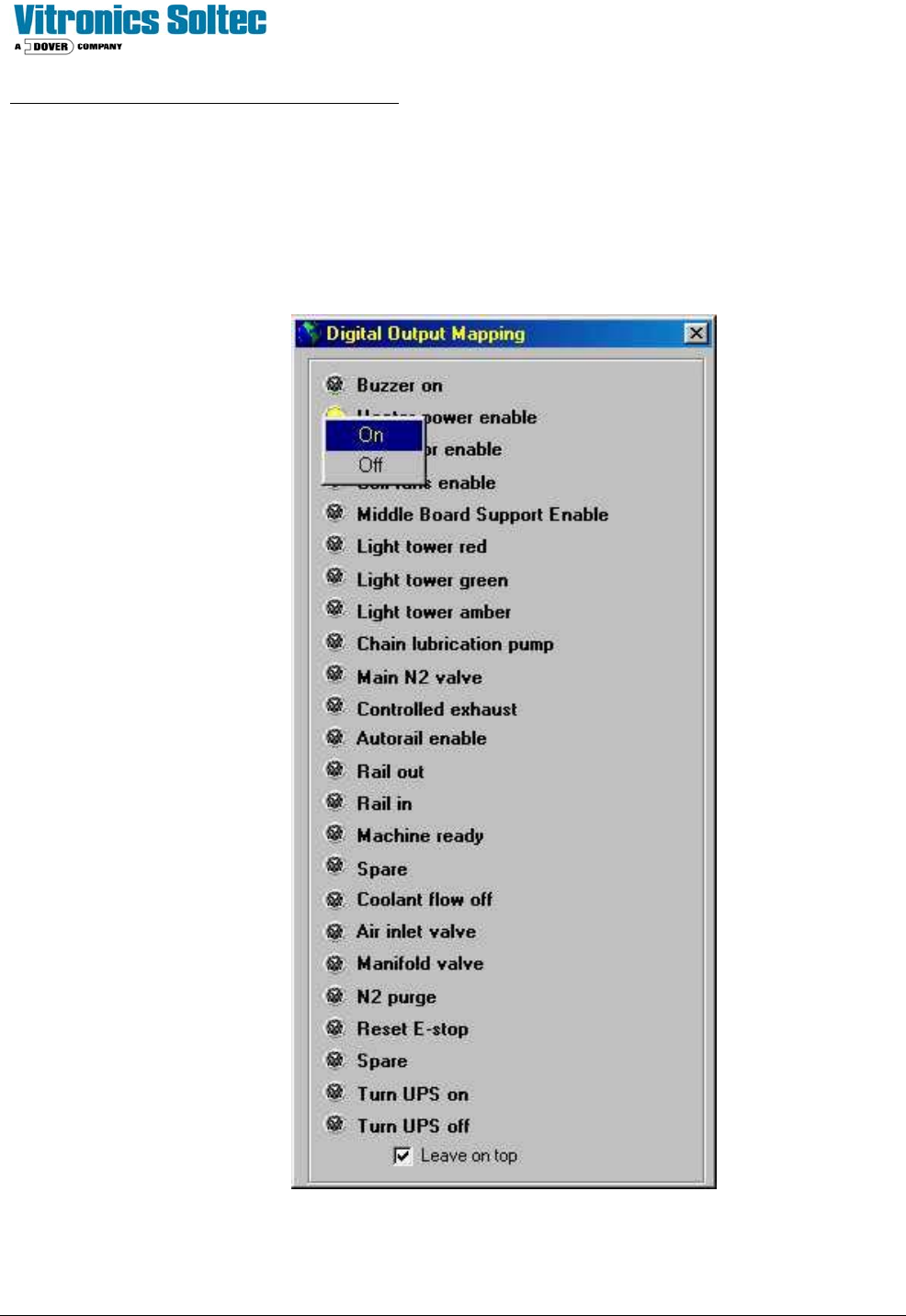
The Input/Output board provides the ability to switch 120 VAC power through interposing relays. The Oven controller
controls the output status of the Input/Output board. Current limiters are installed on all conductors that supply power to
motors. As a diagnostic tool, the Input/Output board outputs may be manually activated one at a time.
See: “Checking Digital Output Status” in the Oven Operation Program.
NOTE: OPEN HEATER CIRCUIT BREAKERS BEFORE TESTING “Heater Power Enable”

Technical Service Manual 86 Revision Date: August 2004
COMPUTER SYSTEM
The computer system must be set up and connected to the Vitronics-Soltec Oven. The monitor and keyboard are placed
on the swing arm / light tower. The keyboard, monitor, and computer connect together. The connections on the back of
the computer are color coded, and they are different sizes/shapes to help connect them properly. (If the keyboard/mouse
does not function, swap the two connectors on the back of the Computer.)
One data cable must be connected from the computer to the oven.
Two 120VAC power cables (they are identical) are factory-wired for the Computer and Monitor. Plug the power cables
into the receptacles on the rear of the Computer and Monitor.
CONTROL CIRCUIT
Test procedure for safety interlock circuit
Þ Activate all circuit breakers.
Þ Ensure all E-stop switches are pulled out.
Þ Log into the Oven control Program and reset the E-Stop Alarm
Þ The E-stop relays K37 & K38 should be energized. If not, check the output of the control transformer using a
Voltmeter at wires #3 and #2. If voltage is present, but K37 & K38 are not energized, there is a break in the series
connection of safety interlocks.
Þ Check that each E-stop and safety interlock switch de-energizes K37 & K38.
Note: The enclosure safety interlock switches mentioned above are optional and do not exist on all ovens.