Technical_reference - 第97页
Technical Service Manual 97 Revision Dat e: August 2004 FUNCTIO N OF T HE FLUX EVACUAT ION SYSTEM N2 Mode - The Flux Flow Control Manifold cr eates a recir culation l oop by draw ing gas fr om the tunnel into the control…
Technical Service Manual 96 Revision Date: August 2004
FLUX EVACUATION SYSTEM
The Flux Evacuation System is:
! Standard, (installed on all ovens) ) An option, (NOT installed on all ovens)
NOTE: The Flux Evacuation System is STANDARD on all N
2
Ovens
PURPOSE
The Vitronics-Soltec Flux Evacuation System is designed to reduce the flow of flux fumes into the cool zones of the
tunnel, resulting in longer maintenance intervals.
APPLICATION
The Flux Evacuation System is the standard gas management system on Vitronics-Soltec ovens equipped with the
Nitrogen option. This configuration is best suited for applications running nearly exclusively nitrogen recipes. The oven is
setup to minimize tunnel maintenance, optimize nitrogen performance, minimize O2 levels, and minimize N2
consumption.
BENEFITS
The XPM
2
series Flux Evacuation System is designed to inhibit the flow of hot flux fumes into the cool zones of the tunnel
(where they can cause maintenance problems), while still optimizing nitrogen performance. This control of gas flow
insures a cleaner cooling zone with maintenance intervals significantly increased. Although widely varying process
parameters will cause individual maintenance intervals to differ, an average expectation should be up to 8 times less
frequent.
The Flux Evacuation System has secondary benefits. In all applications, there should be a noticeable reduction in cooling
zone temperatures. Actual reductions will, of course, be dependent on individual process parameters. The Flux
Evacuation System will not adversely effect nitrogen consumption or 02-PPM levels, as specified by Vitronics Soltec for
XPM
2
series ovens.
It is important to be aware that fan speed settings lower than 2500 RPM will disable the Flux Evacuation System
and will increase flux contamination in the oven
MAINTENANCE
The Flux Evacuation System is virtually maintenance free if operating properly. To ensure this, it is recommended that the
inlet tube from the Flux Flow Control manifold into zone 2 be checked periodically (every three months) for flux residue. If
a flux accumulation is noticed, the flux evacuation manifold may need to be cleaned.
Technical Service Manual 97 Revision Date: August 2004
FUNCTION OF THE FLUX EVACUATION SYSTEM
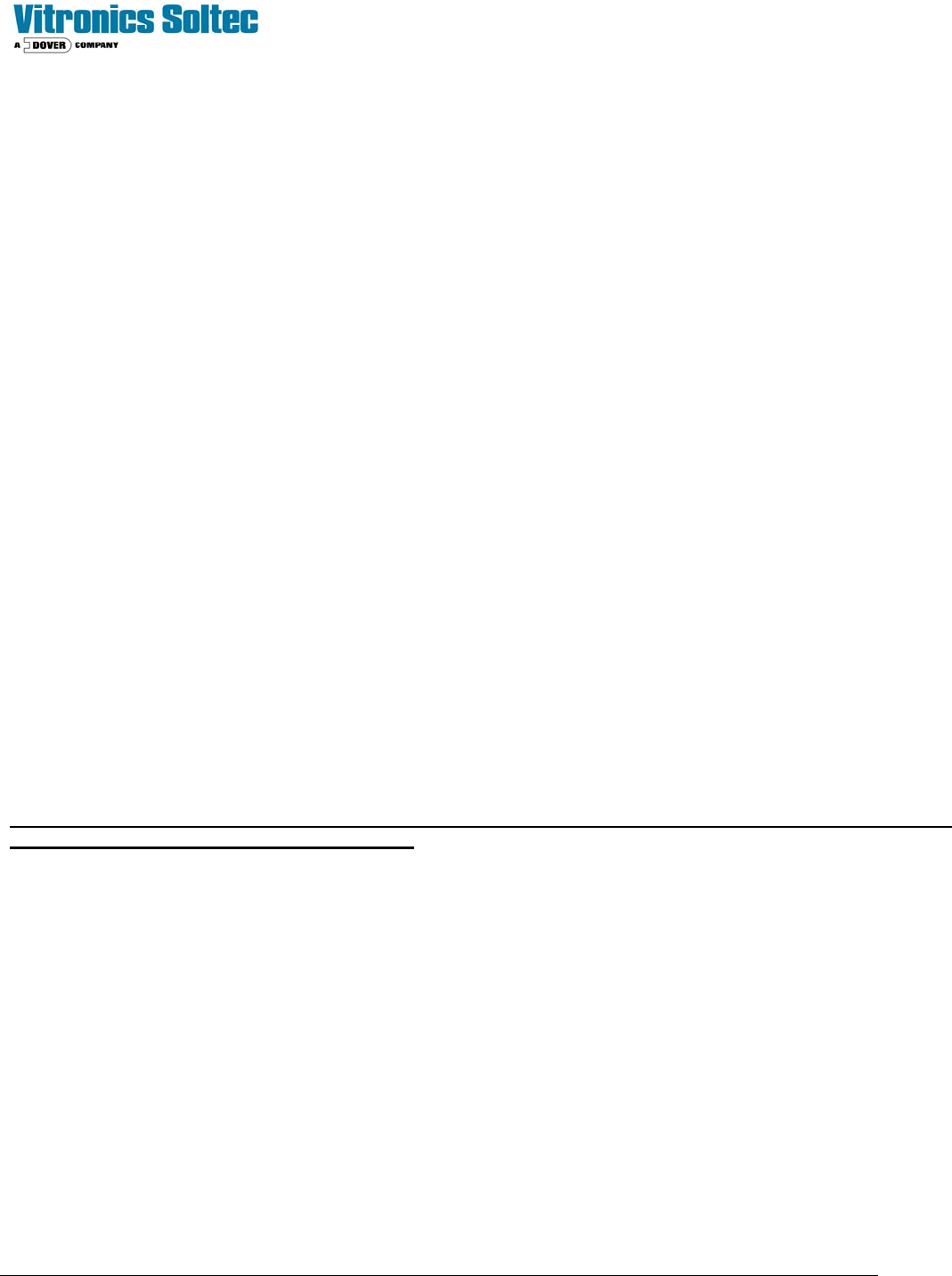
N2 Mode -
The Flux Flow Control Manifold creates a recirculation loop by drawing gas from the tunnel into the controlled exhaust
plenum between the last heat and first cool zones, and returning it to the preheat and soak zones through several of the
patented individual cell inlets. The force powering this recirculation loop is low pressure at the cell inlet, created by the cell
fan. There are no moving parts to this system.
Flow into the controlled exhaust plenum is biased in favor of drawing from the cool zone side. This is accomplished by
raising the pressure in the cool zone (by inputting a high percentage of the total oven nitrogen consumption into that
area), and by reducing the pressure in the last heated zone (by fully opening the individual cell outlet.) The total oven
exhaust is taken from this one port.
The recirculation loop carries low O2 PPM gas from the first cool zone, into the preheat and soak sections of the heated
zone, maintaining low O2 PPMs throughout the tunnel. The recirculation loop carries out flux contaminants trying to enter
the cooling zones. The higher pressure in the cooling zones inhibits the migration of flux contaminants from the heated
zones. The amount of flow into the controlled exhaust from the last heated zone is at a rate that will maintain the total
recirculation loop gas temperature above 120°C, which prevents condensation.
Exhaust flow out of the oven is maximized in volume, and also positioned in the tunnel at the point of highest flux
concentration (the last heated zone), to maximize the amount of flux contaminant per cubic foot of exhaust.
Technical Service Manual 98 Revision Date: August 2004
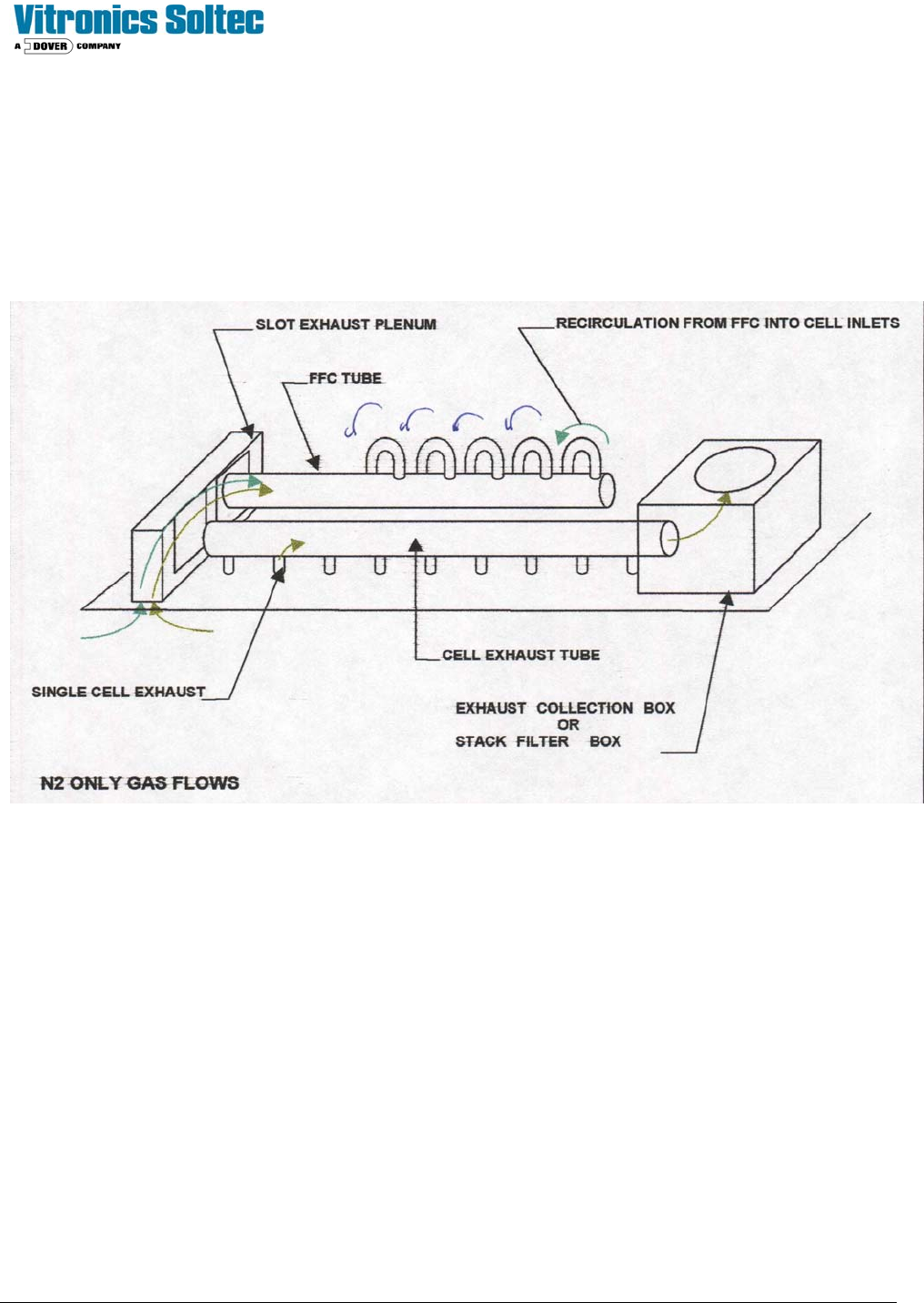
AIR MODE-
The N2 solenoid and the Compressed Air Solenoid will toggle, following the selection of an Air profile by the operator. All
gas flows in the oven remain identical to the N2 Mode, except that Nitrogen is replaced with compressed Air. Flow ratios
and all other process parameters remain identical.
MAINTENANCE
The Flux Flow Control system is virtually maintenance free if operating properly. To ensure this, it is recommended that
the inlet tube from the Flux Flow Control manifold into zone 1 be checked periodically (every six months) for flux residue.
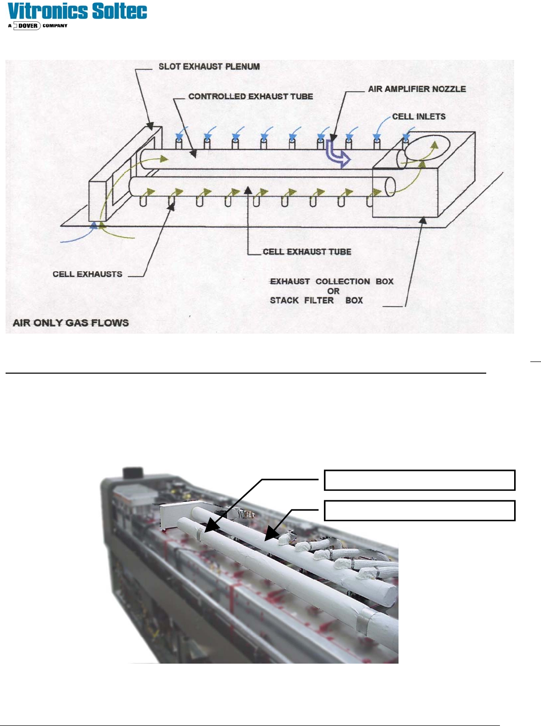
The Flux-Flow Control System is located under the sheet metal skins at the top of the Oven:
Individual Zone Exhaust Duct
Flux Flow Control Duct