三星规格书.pdf - 第23页
Multilayer Ceramic Capacitor - 22 - They should be a good insu lator. They should be non- toxic, and no t produce ha rmful gases, nor be harmfu l when touched. ▶ Application Method It is important to use the proper amoun…
Multilayer Ceramic Capacitor
- 21 -
■
APPLICATION MANUAL
●
Storage of products.
▶
Storage Environment
Tape packing materials are designed to withstand long-term storage, but they will degrade more
rapidly in the presence of high temperature or high humidity, therefor, the products must be
stored in an ambient temperature of less than 40
℃
witharelativehumidityoflessthan70%.
Allowable storage period is within 6 months from the outgoing date of delivery.
▶
Corrosive Gases
Since sulfur and chlorine may degrade the solderability of the end termination, it is important t o
store the capacitors in an environment free of these gases.
▶
Temperature Fluctuations
Since dew condensation may occur by the differences in temperature when the products are
taken out of storage, it is important to maintain a temperature-controlled environment.
●
Design of Solder Land Pattern
When designing priented circuit boards, the shape and size of the solder lands must allow f or
the proper amount of solder on the capacitor. The amount of solder at the end terminations
has a direct effect on the probability that the chip will crack. The greater amount of solder, the
amount of stress on the chip, and the more likely that it will break. Use the following illustrations
as guidelines for proper solder land design.
Recommendation of Solder Land Shape and Size
W b
a
Solder
Land
Solder Resist
2/3W < b < W
T
Solder Resist
2/3T < a < T
●
Adhesives
MlCCs generally require the use of an adhesive to position the chips to the circuit board prior
to soldering.
▶
Requirements for Adhesives
They must have enough adhesion so that the chips will not fall off or move during the handling
of the circuit board.
They must maintain their adhesive strength when exposed to soldering temperature.
They should not spread or run when applied to the circuit board.
They should have a long pot life.
They should harden quickly.
They should not c orrode the circuit board or chip material.
Multilayer Ceramic Capacitor
- 22 -
They should be a good insulator.
They should be non-toxic, and not produce harmful gases, nor be harmful when touched.
▶
Application Method
It is important to use the proper amount of adhesive. Too little will cause poor adhesion to the
circuit board, and too much may strain the conductor pattern, thereb y causing defective soldering.
▶
Adhesive hardening Characteristics
To prevent oxidation of the terminations, the adhesive must harden at 160
℃
or less, within
2 minutes or less.
●
Mounting
▶
Mounting Head Pressure
Excessive pressure will cause chip capacitors to crack. The pressure between nozzle and chip
capacitor will be 300g maximum during mounting.
▶
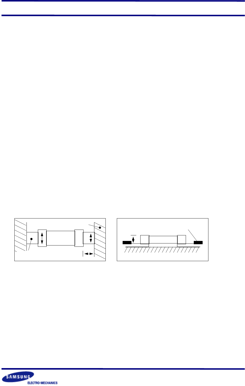
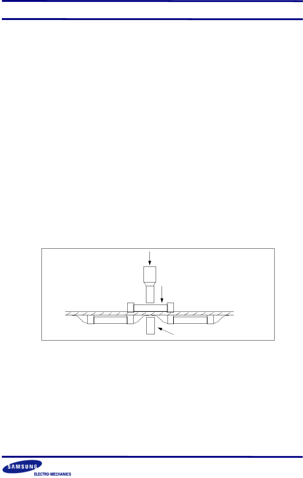
Bending Stress
Bending of printed circuit board by mounting head when double-sided circuit boards are used,
chip capacitors first are mounted and soldered onto one side of the board. When the capacitors
are mounted onto the other side, it is important to support the board as shown in the illustration.
If the circuit board is not supported, it may bend, causing the already-installed capacitors to
crack
support pin
force
nozzle
●
Flux
Although highly-activated flux gives better solderability, substances which increase activity may
also degrade the insulation of the chip capacitors. To avoid such degradation , it is recommended
that a mildly activated rosin flux(less than 0.2% chlorine) be used.
●
Soldering
Since a multilayer ceramic chip capacitor comes into direct contact with melted solder during
soldering, it is exposed to potentially mechanical stress caused by the sudden temperature
change. The capacitor may also be subject to silver migration, and to contamination by the
flux. Because of these factors, soldering technique is critical.
Multilayer Ceramic Capacitor
- 23 -
▶
Soldering Methods
Method Classification
Reflow
soldering
- Overall heating
- Infrared rays
- Hot plate
- VPS(vapor phase)
- Local heating
- Air heater
-Laser
- Light beam
Flow
soldering
- Single wave
- Double wave
-
* W e recommend the reflow soldering method.
▶
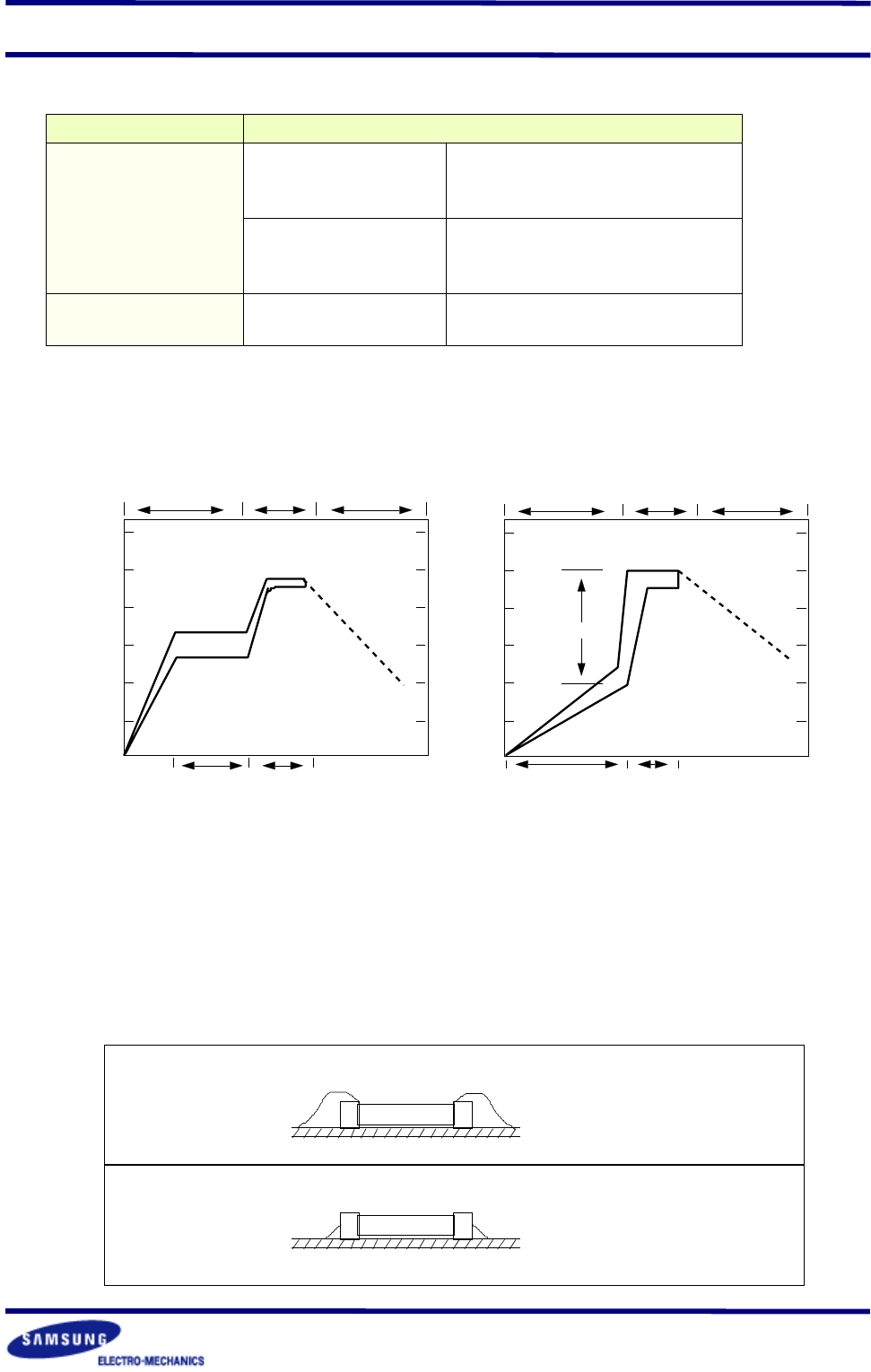
Soldering Profile
To avoid crack problem by sudden temperature change, follow the temperature profile in the
adjacent graph.
300
250
200
150
100
50
℃
preheating soldering cooling
60~120sec 10~20sec
Reflow Soldering
300
250
200
150
100
50
℃
preheating soldering cooling
△
T
≤
150
℃
60~120sec 3~4sec
Flow Soldering
▶
Manual Soldering
Manual soldering c an pose a great risk of creating thermal cracks in chip capacitors. The hot
soldering iron tip comes into direct contact with the end terminations, and operator's carelessness
may cause the tip of the soldering iron to come into direct contact with the ceramic body of
the capacitor. Therefor the soldering iron must be handled carefully, and close attention must
be paid to the selection of the soldering iron tip and to temperature control of the tip.
▶
Amount of Solder
Too much
Solder
Not enough
Solder
Cracks tend to occur due
to large stress
Weak holding force may
cause bad connections or
detaching of the capacitor