三星规格书.pdf - 第24页
Multilayer Ceramic Capacitor - 23 - ▶ Soldering M ethods Method Clas sification Reflow soldering - Overall heating - Infrared rays - Hot plate - VPS(vapor phas e) - Local heating - Air heater -L a s e r - Light beam Flow…
Multilayer Ceramic Capacitor
- 22 -
They should be a good insulator.
They should be non-toxic, and not produce harmful gases, nor be harmful when touched.
▶
Application Method
It is important to use the proper amount of adhesive. Too little will cause poor adhesion to the
circuit board, and too much may strain the conductor pattern, thereb y causing defective soldering.
▶
Adhesive hardening Characteristics
To prevent oxidation of the terminations, the adhesive must harden at 160
℃
or less, within
2 minutes or less.
●
Mounting
▶
Mounting Head Pressure
Excessive pressure will cause chip capacitors to crack. The pressure between nozzle and chip
capacitor will be 300g maximum during mounting.
▶
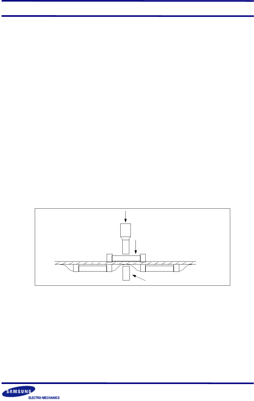
Bending Stress
Bending of printed circuit board by mounting head when double-sided circuit boards are used,
chip capacitors first are mounted and soldered onto one side of the board. When the capacitors
are mounted onto the other side, it is important to support the board as shown in the illustration.
If the circuit board is not supported, it may bend, causing the already-installed capacitors to
crack
support pin
force
nozzle
●
Flux
Although highly-activated flux gives better solderability, substances which increase activity may
also degrade the insulation of the chip capacitors. To avoid such degradation , it is recommended
that a mildly activated rosin flux(less than 0.2% chlorine) be used.
●
Soldering
Since a multilayer ceramic chip capacitor comes into direct contact with melted solder during
soldering, it is exposed to potentially mechanical stress caused by the sudden temperature
change. The capacitor may also be subject to silver migration, and to contamination by the
flux. Because of these factors, soldering technique is critical.
Multilayer Ceramic Capacitor
- 23 -
▶
Soldering Methods
Method Classification
Reflow
soldering
- Overall heating
- Infrared rays
- Hot plate
- VPS(vapor phase)
- Local heating
- Air heater
-Laser
- Light beam
Flow
soldering
- Single wave
- Double wave
-
* W e recommend the reflow soldering method.
▶
Soldering Profile
To avoid crack problem by sudden temperature change, follow the temperature profile in the
adjacent graph.
300
250
200
150
100
50
℃
preheating soldering cooling
60~120sec 10~20sec
Reflow Soldering
300
250
200
150
100
50
℃
preheating soldering cooling
△
T
≤
150
℃
60~120sec 3~4sec
Flow Soldering
▶
Manual Soldering
Manual soldering c an pose a great risk of creating thermal cracks in chip capacitors. The hot
soldering iron tip comes into direct contact with the end terminations, and operator's carelessness
may cause the tip of the soldering iron to come into direct contact with the ceramic body of
the capacitor. Therefor the soldering iron must be handled carefully, and close attention must
be paid to the selection of the soldering iron tip and to temperature control of the tip.
▶
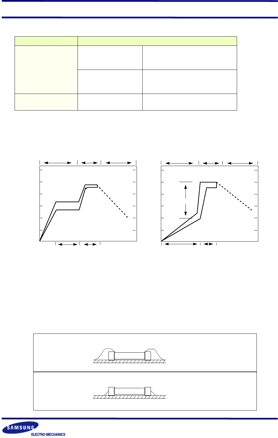
Amount of Solder
Too much
Solder
Not enough
Solder
Cracks tend to occur due
to large stress
Weak holding force may
cause bad connections or
detaching of the capacitor
Multilayer Ceramic Capacitor
- 24 -
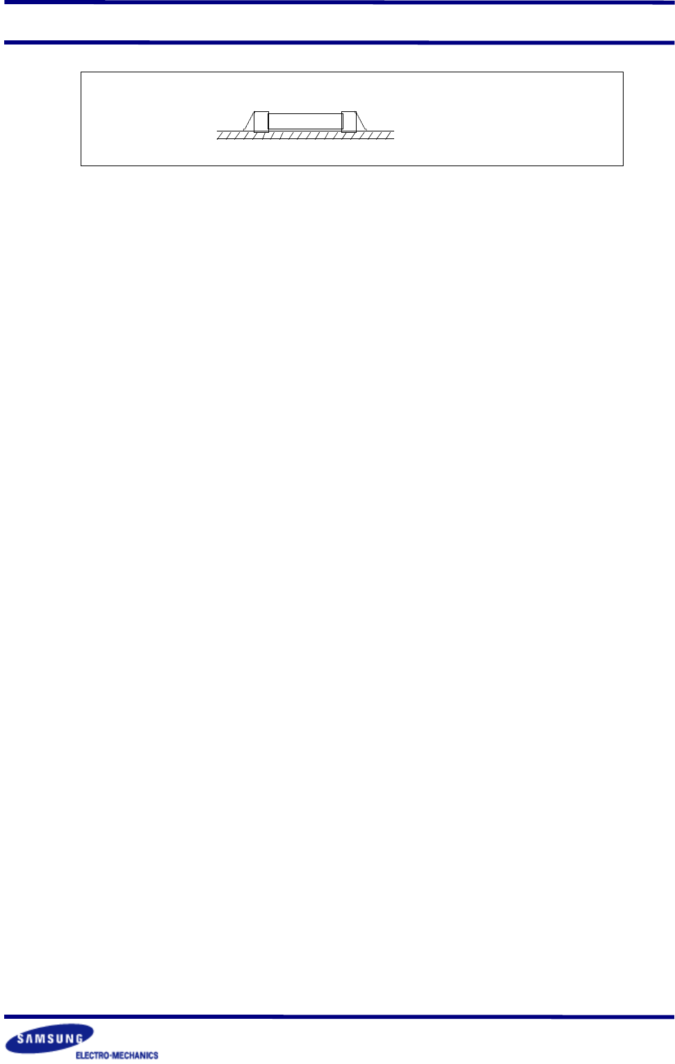
Good
▶
Cooling
Natural cooling using air is recommended. If the chips are dipped into solvent for cleaning,
the temperature difference(
△
T) must be less than 100
℃
6-6. Cleaning
If rosin flux is used, cleaning usually is unnecessary. When strongly activated flux is used,
chlorine in the flux may dissolve into some types of cleaning fluids, thereby affecting the chip
capacitors. This means that the cleaning fluid must be carefully selected, and should always
be new.
▶
Notes for Separating Multiple, Shared PC Boards.
A multi-PC board is separated into many individual circuit boards after soldering has been
completed. If the board is bent or distorted at the time of separation, cracks may occur in the
chip capacitors. Carefully choose a separation method that minimizes the bending of the
circuit board.