三星规格书.pdf - 第25页
Multilayer Ceramic Capacitor - 24 - Good ▶ Cooling Natural coolin g using air is recom mended. If the chips are dipped int o solvent fo r cleaning, the temperature difference( △ T) must be less than 100 ℃ 6-6. Cleaning I…
Multilayer Ceramic Capacitor
- 23 -
▶
Soldering Methods
Method Classification
Reflow
soldering
- Overall heating
- Infrared rays
- Hot plate
- VPS(vapor phase)
- Local heating
- Air heater
-Laser
- Light beam
Flow
soldering
- Single wave
- Double wave
-
* W e recommend the reflow soldering method.
▶
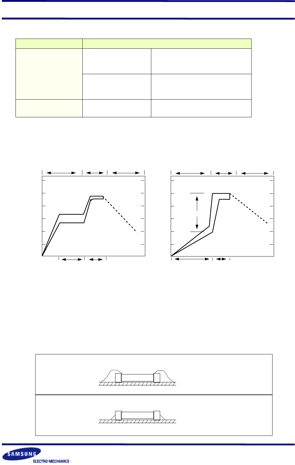
Soldering Profile
To avoid crack problem by sudden temperature change, follow the temperature profile in the
adjacent graph.
300
250
200
150
100
50
℃
preheating soldering cooling
60~120sec 10~20sec
Reflow Soldering
300
250
200
150
100
50
℃
preheating soldering cooling
△
T
≤
150
℃
60~120sec 3~4sec
Flow Soldering
▶
Manual Soldering
Manual soldering c an pose a great risk of creating thermal cracks in chip capacitors. The hot
soldering iron tip comes into direct contact with the end terminations, and operator's carelessness
may cause the tip of the soldering iron to come into direct contact with the ceramic body of
the capacitor. Therefor the soldering iron must be handled carefully, and close attention must
be paid to the selection of the soldering iron tip and to temperature control of the tip.
▶
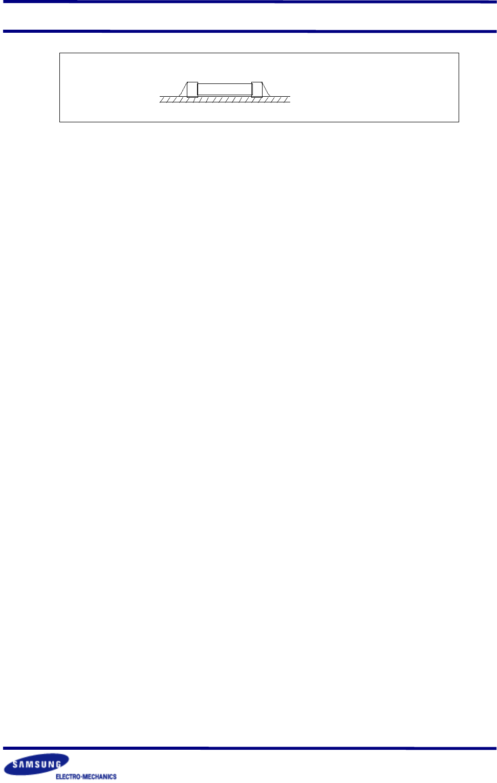
Amount of Solder
Too much
Solder
Not enough
Solder
Cracks tend to occur due
to large stress
Weak holding force may
cause bad connections or
detaching of the capacitor
Multilayer Ceramic Capacitor
- 24 -
Good
▶
Cooling
Natural cooling using air is recommended. If the chips are dipped into solvent for cleaning,
the temperature difference(
△
T) must be less than 100
℃
6-6. Cleaning
If rosin flux is used, cleaning usually is unnecessary. When strongly activated flux is used,
chlorine in the flux may dissolve into some types of cleaning fluids, thereby affecting the chip
capacitors. This means that the cleaning fluid must be carefully selected, and should always
be new.
▶
Notes for Separating Multiple, Shared PC Boards.
A multi-PC board is separated into many individual circuit boards after soldering has been
completed. If the board is bent or distorted at the time of separation, cracks may occur in the
chip capacitors. Carefully choose a separation method that minimizes the bending of the
circuit board.
Multilayer Ceramic Capacitor
- 25 -
■
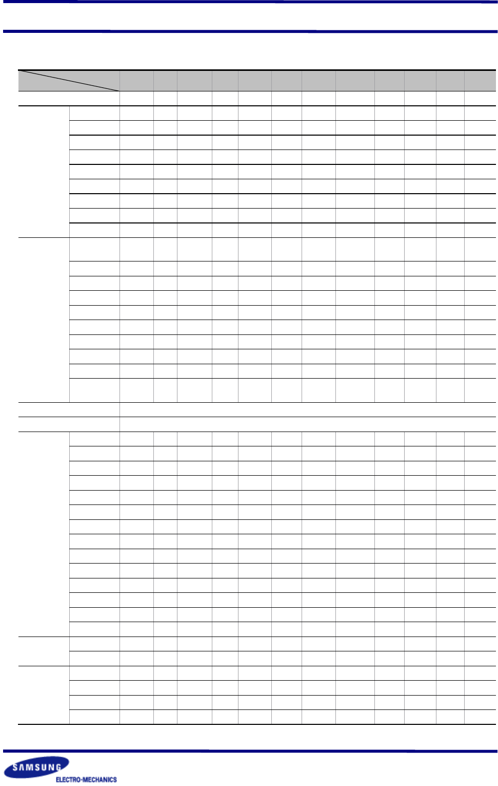
CROSS REFERENCE
P/N COMPANY SAMSUNG AVX
JOHANSO
N
KEMET KYOCE RA MURATA NOVACAP PANASONIC ROHM
TAIYO
- YUDEN
TDK
VITRAMO
N
①
COMPANY MODEL(MLCC)
CL - - C CM GRM - ECJ MCH MK C VJ
②
SIZE
(EIA/JIS)
0201(0603)
03 - - - 03 33 - Z - 063 0603 -
0402(1005)
05 0402 R07 0402 05 36 0402 0 15 105 1005 0402
0603(1608)
10 0603 R14 0603 105 39 0603 1 18 107 1608 0603
0805(2012)
21 0805 R15 0805 21 40 0805 2 21 212 2012 0805
1206(3216)
31 1206 R18 1206 316 42-6 1206 3 31 316 3216 1206
1210(3225)
32 1210 S41 1210 32 42-2 1210 4 32 325 3225 1210
1808(4520)
42 1808 R29 1808 42 - 1808 - - - 4520 1808
1812(4532)
43 1812 S43 1812 43 43-2 1812 - 43 432 4532 1812
2220(5750)
55 - - 2220 55 44-1 2221 - - 550 5650 -
③
TEMPERATURE
CHARACTERISTIC
COG(NPO)
C A N G CG COG/CH N C A C COG/CH A
P2H(N150)
P S - - P P2H - P - P PH -
R2H(N220)
R 1 - - R R2H - R - R RH -
S2H(N330)
S 3 - - S S2H - S - S SH -
T2H(N470)
T O - - T T2H - T - T TH -
U2J(N750)
U Z - - U U2J - U UJ U UJ -
S2L
L Y - - SL SL - G SL SL SL -
X7R
B C W R(X) X7R X7R B B C BJ X7R(B) Y(X)
Z5U
E E Z U - Z5U Z - E - Z5U U
Y5V
F G Y V Y5V Y5V Y F F F Y5V -
④
NOMINAL CAPACITANCE
EX) 103=10,000
㎊
221=220
㎊
225=2,200,000
㎊
=2.2
㎌
1R5=1.5
㎊
010=1
㎊
⑤
CAPACITANCE TOLERANCE
B:
±
0.1
㎊
C:
±
0.25
㎊
D:
±
0.5
㎊
F:
±
1% G:
±
2% J:
±
5% K:
±
10% M:
±
20% Z:-20~+80%
⑥
RATED
VOLTAGE
6.3V
Q 6 - 9 06 6.3 - 0J - J 0J -
10 V
P Z 100 8 10 10 - 1A 4 L 1A -
16 V
O Y 160 4 16 16 160 1C 3 E 1C J
25 V
A 3 250 3 25 25 250 1E 2 T 1E X
50 V
B 5 500 5 50 50 500 1H 5 U 1H A
100 V
C 1 101 1 100 100 101 2A 1 - 2A B
200V
D 2 201 2 200 200 201 2D - - - C
250V
E V - - 250 250 251 - - - 2E -
500V
G 7 501 - 500 500 501 - - - - E
630V
H - - - 630 630 - - - - 2J -
1000V
I A 102 - 1000 1K 102 - - - 3A G
2000V
J G 202 - 2000 2K 202 - - - 3D -
3000V
K H 302 - 3000 3K 302 - - - 3F H
4000V
- J - 4000 - 402 - - - - -
⑦
TERMINATION
NICKEL BARRIER
N T V C A (GRM) N - (MCH) - - X
Ag/Pd
P 1 - - B (GR) P - (MC) - - F
⑧
PACKAGE
BULK(VINYL)
B 9 (NONE) - B PB * X - B B B
PAPER TAPING
C 2, 4 T, R - T, L PT T E,V,W K, L T T C, P
PLASTIC TAPING
E 1, 3 E, U - H, N PT - F, Y P, Q T - T, R
BULK CASE
P 7 - - C PC - C C - - G