三星规格书.pdf - 第5页
Multilayer Ceramic Capacitor - 4 - ■ PART NUMBERING Symbo l EIA Code Temperature Coefficient(PPM/ ℃ ) ※ Temperature Characteristics Operation Temperature Range C C0G 0 ± 30 C Δ -55 ~ +125 ℃ P PH -150 ± 60 P Δ R RH -220 ±…
Multilayer Ceramic Capacitor
- 3 -
■
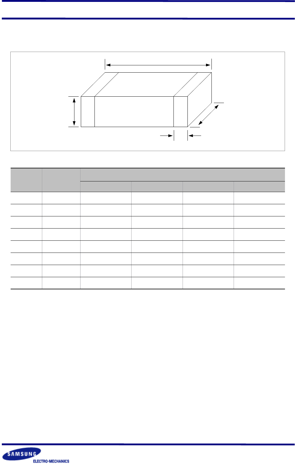
APPEARANCE AND DIMENSION
L
BW
T
W
CODE EIA CODE
DIMENSION ( mm )
L W T(MAX) BW
03
0201
0.6
±
0.03 0.3
±
0.03 0.3
±
0.03 0.15
±
0.05
05
0402
1.0
±
0.05 0.5
±
0.05 0.5
±
0.05 0.2+0.15/-0.1
10
0603
1.6
±
0.1 0.8
±
0.1 0.8
±
0.1 0.3
±
0.2
21
0805
2.0
±
0.1 1.25
±
0.1 1.25
±
0.1 0.5+0.2/-0.3
31
1206
3.2
±
0.2 1.6
±
0.2 1.6
±
0.2 0.5+0.2/-0.3
32
1210
3.2
±
0.3 2.5
±
0.2 2.5
±
0.2 0.6
±
0.3
43
1812
4.5
±
0.4 3.2
±
0.3 3.2
±
0.3 0.8
±
0.3
55
2220
5.7
±
0.4 5.0
±
0.4 3.2
±
0.3 1.0
±
0.3
Multilayer Ceramic Capacitor
- 4 -
■
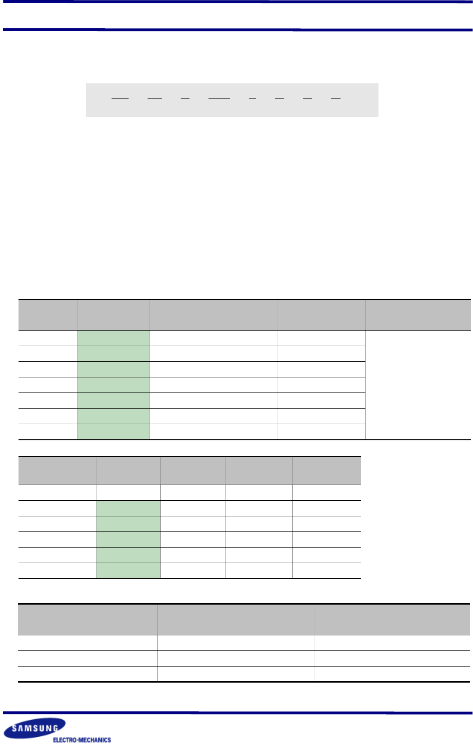
PART NUMBERING
Symbol EIA Code
Temperature
Coefficient(PPM/
℃
)
※
Temperature
Characteristics
Operation
Temperature Range
C
C0G 0
±
30 C
Δ
-55 ~ +125
℃
P
PH -150
±
60 P
Δ
R
RH -220
±
60 R
Δ
S
SH -330
±
60 S
Δ
T
TH -470
±
60 T
Δ
U
UJ -750
±
120 U
Δ
L
SL +350 ~ -1000 SL
▶
CLASS
Ⅰ
(Temperature Compensation)
Temperature
Characteristics
below 2.0pF 2.2 ~ 3.9pF above 4.0pF above 10pF
C
Δ
C0G
C0G C0G C0G
P
Δ
- PJ PH PH
R
Δ
- RJ RH RH
S
Δ
- SJ SH SH
T
Δ
- TJ TH TH
U
Δ
- UJ UJ UJ
Symbol EIA Code
Capacitance Change
(
Δ
C:%)
Operation
Temperature Range
A
X5R
±
15
-55 ~ +85
℃
B
X7R
±
15
-55 ~ +125
℃
F
Y5V
+22 ~ -82 -30 ~ +85
℃
▶
CLASS
Ⅱ
(High Dielectric Constant)
SAMSUNG Multilayer Ceramic Chip Capacitor
Type(Size)
Capacitance Temperature Characteristics
Nominal Capacitance
Capacitance Tolerance
Rated Voltage
Thickness Option
Packaging Type
CL10C101JBNC
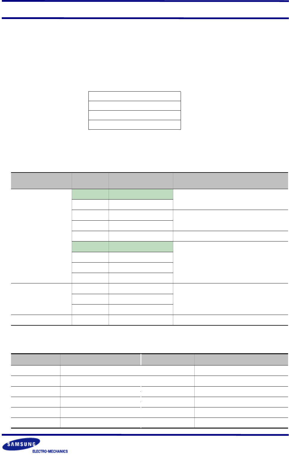
CAPACITANCE TEMPERATURE CHARACTERISTICS
※
Temperature Characteristics
☞
J:
±
120 PPM/
℃
H:
±
60 PPM/
℃
G:
±
30 PPM/
℃
●
3
●
7
●
8
●
2
●
6
●
3
●
4
●
5
●
2
●
6
●
3
●
4
●
5
●
7
●
8
●
1
●
1
Multilayer Ceramic Capacitor
- 5 -
Temperature
Characteristies
Symbol Tolerance Applicable Capacitance & Range
C0G(NPO)
or
T.C Series
A
±
0.05pF
0.5 ~ 3pF
B
±
0.1pF
C
±
0.25pF
0.5 ~ 10pF
D
±
0.5pF
F
±
1pF
6 ~ 10pF
F
±
1%
E-24 Series for over 10pF
G
±
2%
J
±
5%
K
±
10%
A(X5R)
B(X7R)
J
±
5%
E-12 SeriesK
±
10%
M
±
20%
F(Y5V)
Z
-20% ~ +80% E-6 Series
※
Please Consult us for special tolerances.
Symbol Rated Voltage(Vdc) Symbol Rated Voltage(Vdc)
R
4V
C
100V
Q
6.3V
D
200V
P
10V
G
500V
O
16V
I
1000V
A
25V
J
2000V
B
50V
K
3000V
RATED VOLTAGE
CAPACITANCE TOLERANCE
The nominal capacitance value is expressed in pico-Farad(pF) and identified by three-
digit number, first two digits represent significant figures and last digit specifies the
number of zeros to follow. For values below 1pF, the letter "R" is used as the decimal
point and the last digit becomes significant.
example)
100 : 10
×
10
o
=10pF
102 : 10
×
10
2
= 1000pF
020 : 2
×
10
o
=2pF
1R5 : 1.5pF
NOMINAL CAPACITANCE
●
5
●
6
●
4