Printer 710_810 v8 High Throughput Conveyor Module.pdf - 第11页
HIGH THROUG HPUT CONVE YOR (HTC ) MODULE ADJUS TMENT S AND SET TINGS Chapter Issue 3 Oct 06 Technical Reference Manual 17.11 5. T urn the board 90° an d position back onto t he rail syst em, (so that the board lies on to…
HIGH THROUGHPUT CONVEYOR (HTC) MODULE
ADJUSTMENTS AND SETTINGS
17.10 Technical Reference Manual Chapter Issue 3 Oct 06
Sensitivity
Adjustment
When fitted to the machine rails the diffuse sensors switching threshold can be
adjusted by means of a sensitivity control switch. This ensures that when a
board is fed into the machine (via the transport belts) the sensor output switches
to ON.
To achieve an optimum setting carry out the following procedure:
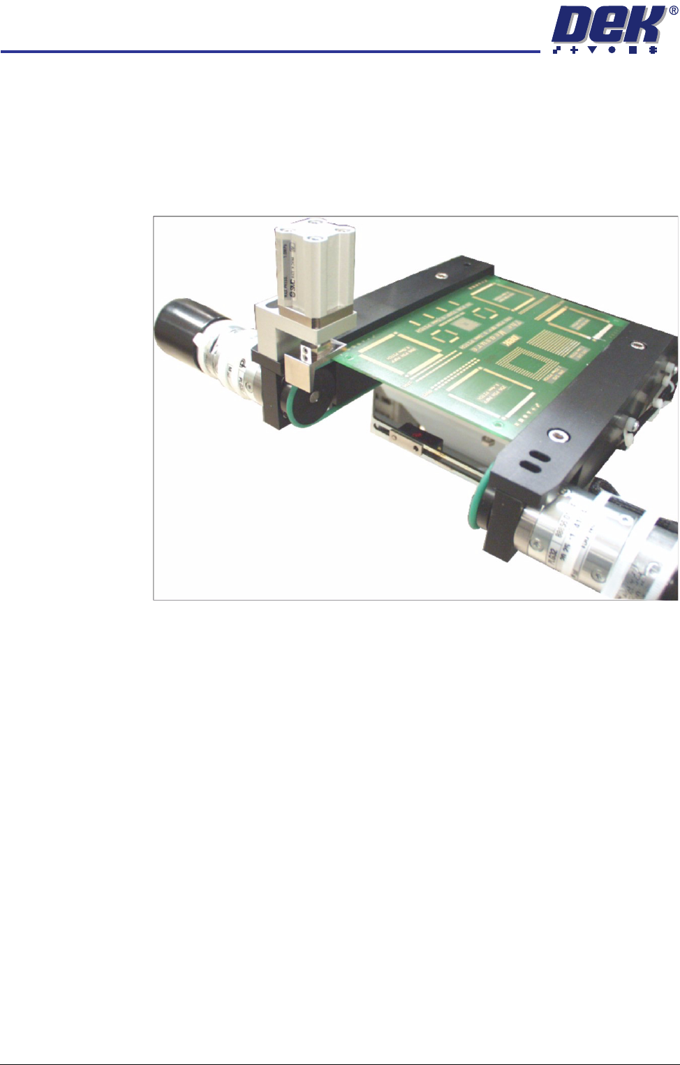
1. Place a board on the rails covering the sensor.
2. Turn the sensitivity control fully anti-clockwise, ensure that the amber LED
is extinguished.
3. Re-adjust the sensitivity control clockwise until the amber LED illuminates.
NOTE
If the amber LED is flashing, this indicates a week signal. Re-adjust the
sensitivity control.
4. Remove the board from the rails and confirm the amber LED extinguishes.
HIGH THROUGHPUT CONVEYOR (HTC) MODULE
ADJUSTMENTS AND SETTINGS
Chapter Issue 3 Oct 06 Technical Reference Manual 17.11
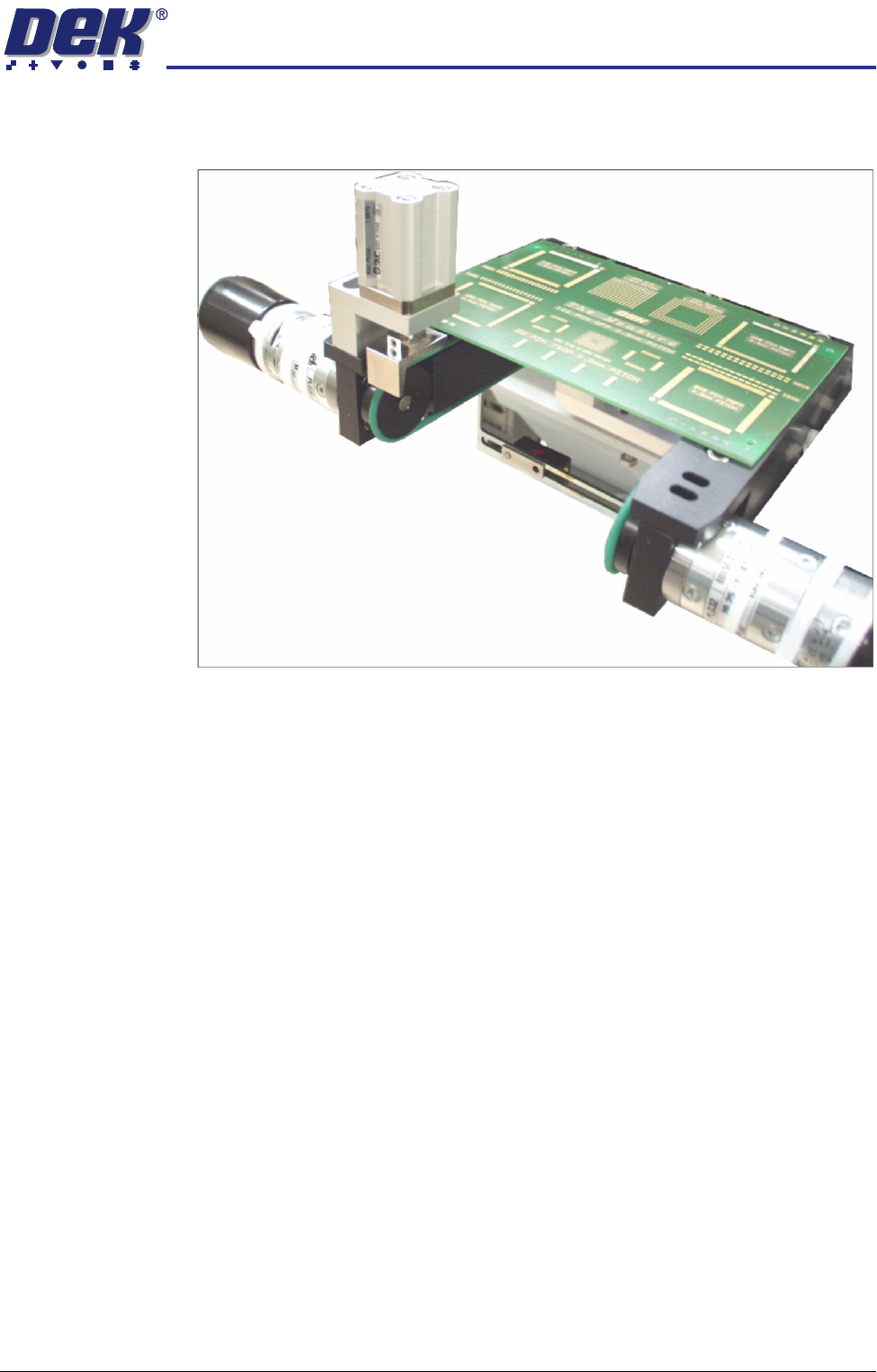
5. Turn the board 90° and position back onto the rail system, (so that the board
lies on top of the rail system as shown in the figure below).
6. Confirm that the amber LED is extinguished. If the amber LED illuminates,
turn the sensitivity control anti-clockwise until the amber LED extinguishes.
7. Remove the board.
8. Position the board back on the rail system, as in Step 1, and confirm that the
amber LED illuminates.
9. Remove the board from the rails and confirm that the amber LED extin-
guishes.
10. This completes the adjustment. If the board has holes or cut-outs, continue
with this procedure.
11. Slide the board backward and forward across the sensor ensuring that the
LED is only triggered by the leading and trailing edges of the board.
12. If the LED flickers when encountering holes or cut-outs, turn the sensitivity
control clockwise a further quarter turn.
13. Repeat Steps 11 and 12 until the correct setting is achieved.
14. Remove the board from the rails and confirm that the amber LED extin-
guishes.
HIGH THROUGHPUT CONVEYOR (HTC) MODULE
ADJUSTMENTS AND SETTINGS
17.12 Technical Reference Manual Chapter Issue 3 Oct 06
Print Station Front Rail Parallelism
WARNING
BOARD CLAMPS. EXTREME CARE MUST BE EXERCISED WHEN WORKING IN
THE TOOLING AREA OF THE MACHINE TO AVOID INJURY. THE FOILS ON THE
FRONT AND REAR BOARD CLAMPS ARE VERY SHARP.
NOTE
The Print Station Front Rail Parallelism is factory set and shouldn’t normally
need to be adjusted.
1. In Rising Table Diagnostics, select Raise Table to Vision Height.
2. In Rail System Diagnostics, select Toggle Board Clamp, to release the
clamps.
3. Open the front printhead cover/shutter.
4. Remove the board clamp from the front transport rail.
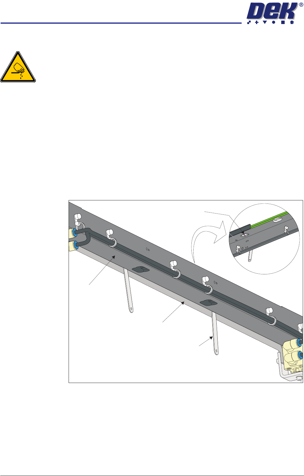
5. Using feeler gauges from the underside of the front rail, check the gap
between the belt support plate and the main rail, as close as possible to both
linear guides. Make a note of the measured gaps (0.65mm ±0.15mm).
6. Place appropriate feeler gauges (the measured gap) in the gap between the
belt support plate and the main rail as close as possible to the board clamp
View on Top of Front Rail
View on Underside of Front Rail
Linear Guide
Feeler Gauge
(in 2 positions)
Belt Support Plate
Main Rail