Printer 710_810 v8 High Throughput Conveyor Module.pdf - 第14页
HIGH THROUG HPUT CONVEY OR (HTC) MOD ULE ADJUS TMEN TS AND SE TTINGS 17.14 Technical Reference Manual Chapter Issue 3 Oct 06 8. Place the r ail locatio n jig onto th e rising t able, so that the ali gnment p ads abut the…
HIGH THROUGHPUT CONVEYOR (HTC) MODULE
ADJUSTMENTS AND SETTINGS
Chapter Issue 3 Oct 06 Technical Reference Manual 17.13
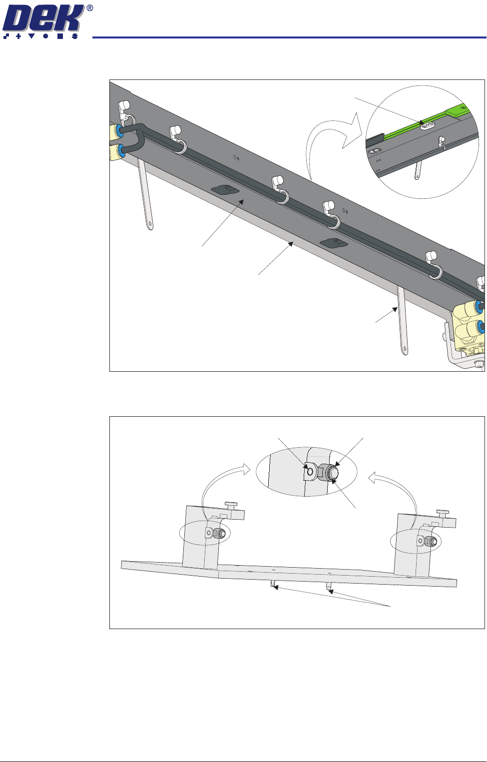
locating plates. This prevents any flexing of the belt support plate.
7. On the rail location jig (DEK Pt No 183288) ensure the alignment pads are
fitted in the correct position.
View on Underside of Front Rail
View on Top of Front Rail
Board Clamp Locating Plate
Feeler Gauge
(in 2 positions)
Belt Support Plate
Main Rail
Location Jig
6mm Locating Pins
Alignment Pad
Heavy Board
Rails Position
Standard Rails
Position
HIGH THROUGHPUT CONVEYOR (HTC) MODULE
ADJUSTMENTS AND SETTINGS
17.14 Technical Reference Manual Chapter Issue 3 Oct 06
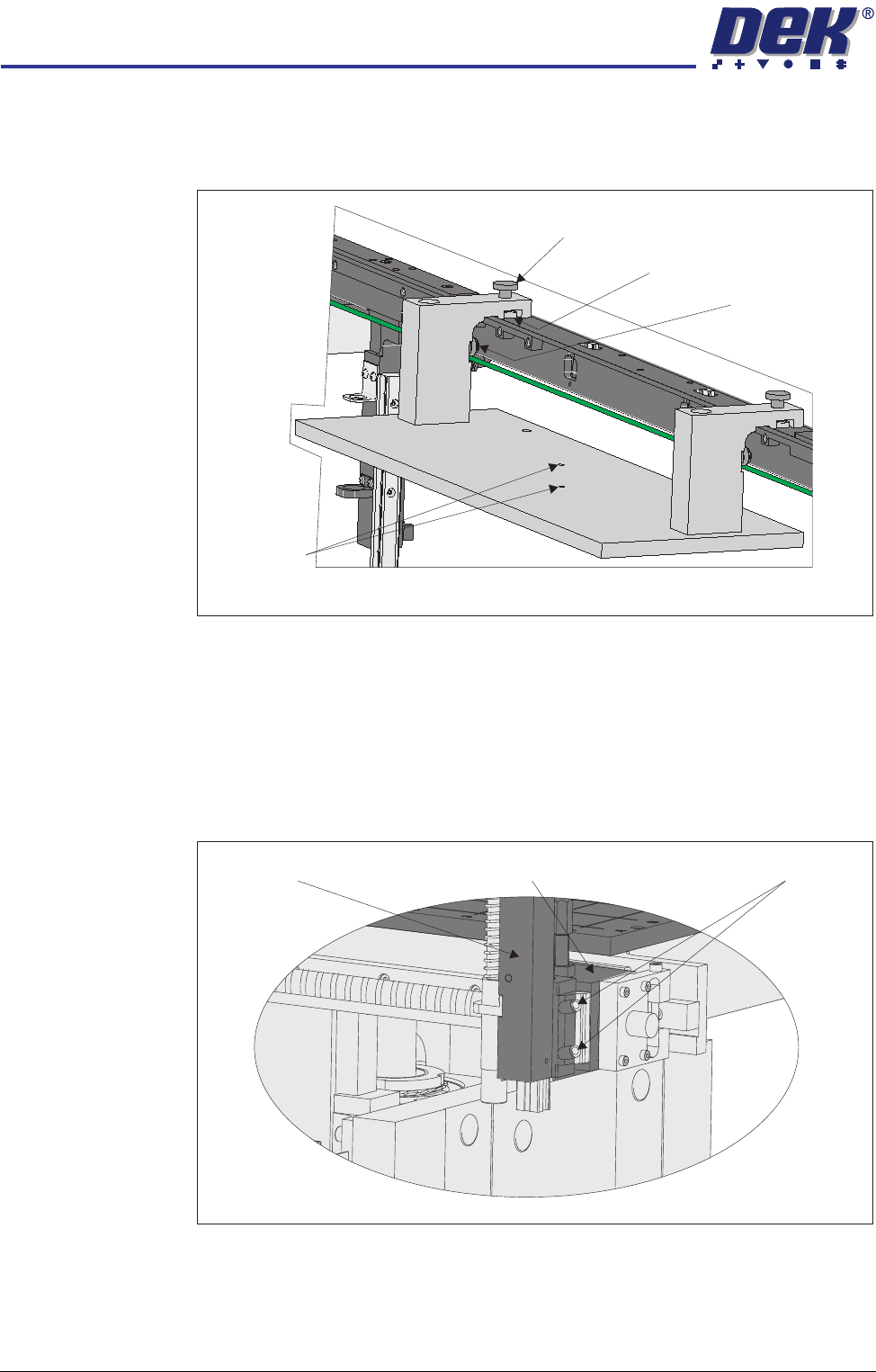
8. Place the rail location jig onto the rising table, so that the alignment pads
abut the rear of the front rail and the two 6mm locating pins fit into the
corresponding holes on the rising table.
9. Secure the location jig to the front rail using the two thumbscrews on the
location jig.
10. Using a feeler gauge check that the gap between the alignment pads and
the front rail is less than 0.05mm.
11. If adjustment is not necessary continue with Step 23.
12. Using a 3mm Allen key slacken the four securing bolts attaching the left
hand transport leg to the carriage nut.
13. Repeat Step 12 on the right hand transport leg.
View on Rear of Front Rail
Alignment Pad
(2 positions)
Thumbscrew (2 positions)
Location Plate (2 positions)
Locating Pins
View on Front of Fixed Rail
Carriage Nut Securing BoltsTransport Leg
HIGH THROUGHPUT CONVEYOR (HTC) MODULE
ADJUSTMENTS AND SETTINGS
Chapter Issue 3 Oct 06 Technical Reference Manual 17.15
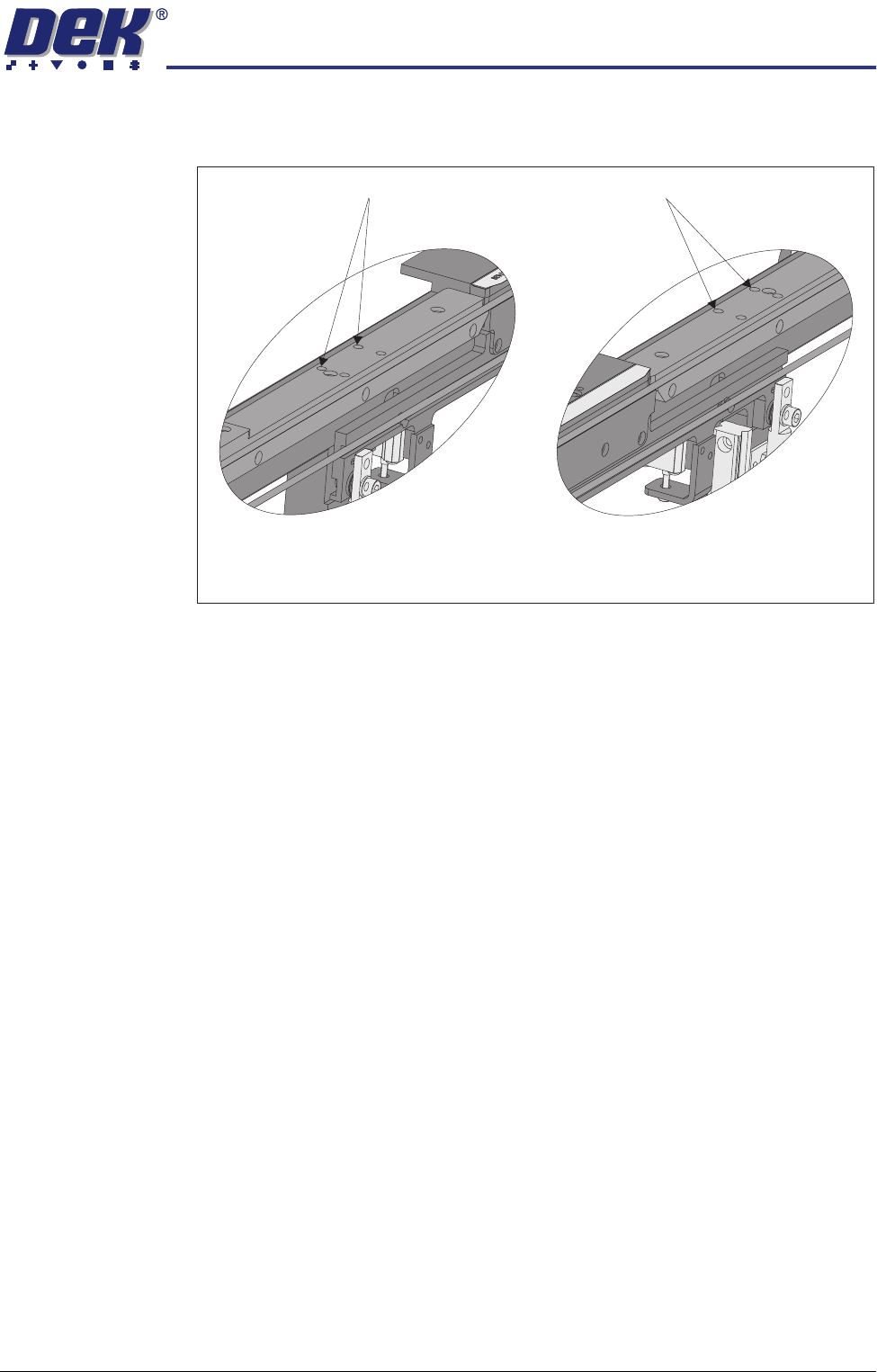
14. Using a 4mm Allen key, through the access holes in the board edge guide,
slacken the four rail securing bolts (two each side).
15. Loosen the two thumbscrews on the location jig.
16. Adjust the front rail position to achieve the settings in Step 10.
17. Tighten the two thumbscrews on the location jig, recheck the parallelism.
18. Tighten the bolts slackened in Steps 12 to 14, recheck the parallelism.
19. When the adjustment is complete, remove the board edge guides from each
end of the rail.
20. Remove each bolt disturbed (one at a time), apply a suitable locking
compound and fully tighten.
21. Refit the board edge guide to each end of the rail.
22. Carry out Camera X Axis Parallelism and Print Station Rear Rail Parallelism
(Technical Reference Manual, Camera System Module Chapter and this
chapter refers).
23. Remove all feeler gauges from the front rail.
24. Remove the location jig from the rising table.
25. Fit the board clamp to the front rail.
Access Holes
View on Inside of Front Rail
Left Hand End
View on Inside of Front Rail
Right Hand End
Access Holes