Printer 710_810 v8 High Throughput Conveyor Module.pdf - 第30页
HIGH THROUG HPUT CONVEY OR (HTC) MOD ULE ADJUS TMEN TS AND SE TTINGS 17.30 Technical Reference Manual Chapter Issue 3 Oct 06 5. Using a spi rit leve l, place across both sett ing plates and check the pla tes are lev el. …
HIGH THROUGHPUT CONVEYOR (HTC) MODULE
ADJUSTMENTS AND SETTINGS
Chapter Issue 3 Oct 06 Technical Reference Manual 17.29
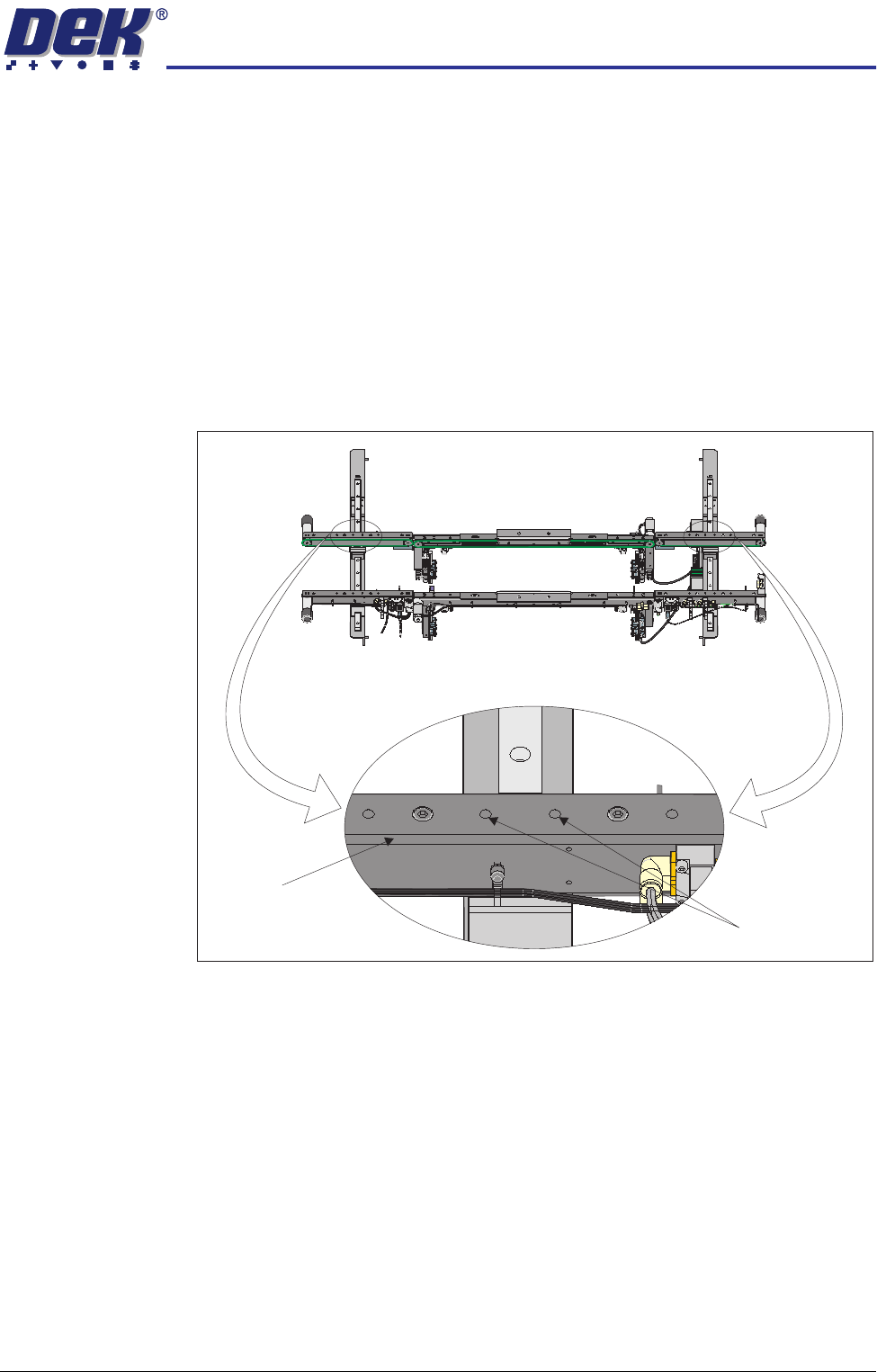
4. Place a 0.5mm feeler gauge between the plate and the inner face of the
auxiliary conveyor rear rail.
5. Run the feeler gauge along the whole length of the conveyor rail, the fit of
the feeler gauge should be tight, between the plate and the inner face of the
rail.
6. Remove the feeler gauge and manually move the plate in and out of the
machine along the conveyor transport belts, ensuring the plate moves freely
without binding or jamming.
If adjustment is required, carry out the following:
7. Loosen the two rear rail securing bolts, adjust the rail to achieve parallelism
and re-tightening the rail securing bolts.
8. Repeat Steps 3 - 6 to recheck for parallelism.
9. Repeat Steps 3 - 8 for the left hand auxiliary conveyor.
Auxiliary Conveyor
Height Setting
To check and if required adjust the height of the auxiliary conveyor to the print
station rails carry out the following at transport height:
1. In Rail System Diagnostics, select Adjust and alter board width to 250mm.
2. Select Drive Rail to Board Width. The rails are driven to the board width
selected.
3. Using a Board Clamp Setting Plate Pt No 140403, place the plate on the
auxiliary conveyor transport belts.
4. Place a second board clamp setting plate onto the transport belts of the print
station. Ensure the plates abut and are fully supported by the transport
belts.
Front View of HTC Rails
Auxiliary Conveyor
Rear Rail
Rear Rail
Securing Bolts
HIGH THROUGHPUT CONVEYOR (HTC) MODULE
ADJUSTMENTS AND SETTINGS
17.30 Technical Reference Manual Chapter Issue 3 Oct 06
5. Using a spirit level, place across both setting plates and check the plates
are level.
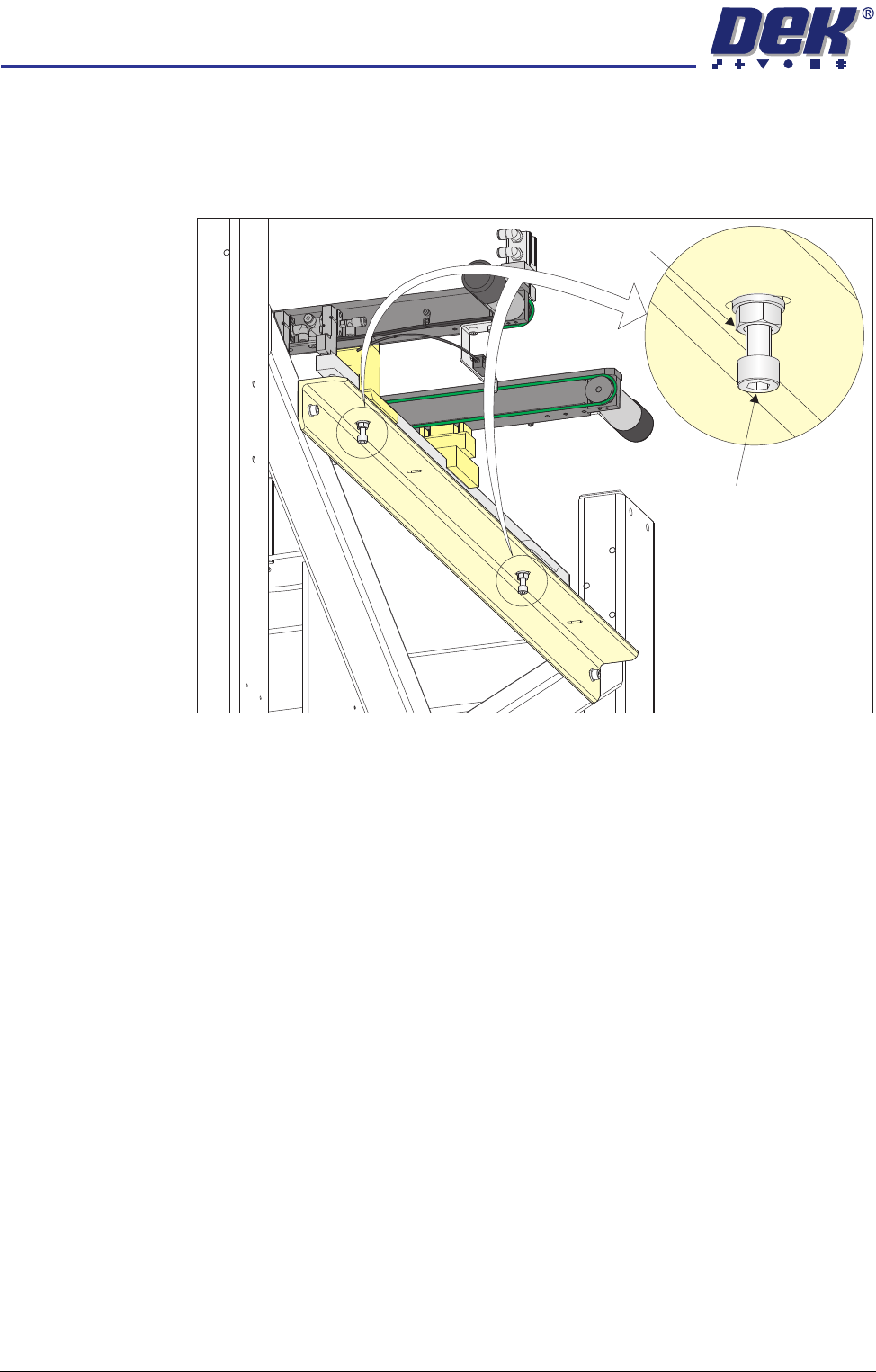
6. If adjustment is required, loosen the two locking nuts on the auxiliary
conveyor height adjustment bolts.
7. To alter the height of the conveyor carefully adjust both height adjustment
bolts.
8. Carefully adjust the height of the conveyor rails until they match the print
station rails.
9. Re-tighten the locking nuts loosened in Step 6 and repeat the check.
10. If adjustment has occurred, carry out Auxiliary Conveyor Levelling check.
Auxiliary Conveyor
Height Adjustment
Bolt
Locking Nut
HIGH THROUGHPUT CONVEYOR (HTC) MODULE
REPLACEMENT PROCEDURES
Chapter Issue 3 Oct 06 Technical Reference Manual 17.31
REPLACEMENT PROCEDURES
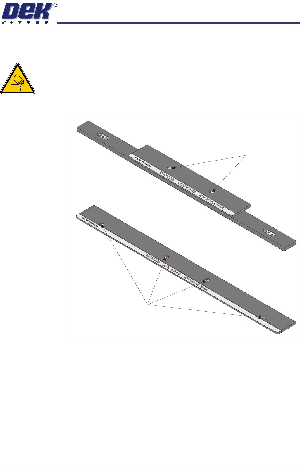
Board Clamp Replacement
WARNING
BOARD CLAMPS. EXTREME CARE MUST BE EXERCISED WHEN WORKING IN
THE TOOLING AREA OF THE MACHINE TO AVOID INJURY. THE FOILS ON THE
FRONT AND REAR BOARD CLAMPS ARE VERY SHARP.
1. Remove the board clamp securing screws and remove the board clamp.
Retain the screws.
2. Place the new board clamp in position on the location plates.
3. Secure the board clamp in position with the screws removed in Step 1.
NOTE
The Board Clamp Setting procedure is not required after board clamp
replacement.
500mm Board Clamp Mechanism
Board Clamp Securing Screws
250mm Board Clamp Mechanism
Board Clamp Securing Screws