Printer 710_810 v8 High Throughput Conveyor Module.pdf - 第38页
HIGH THROUG HPUT CONVEY OR (HTC) MOD ULE REP LAC EMEN T PR OCE DURE S 17.38 Technical Reference Manual Chapter Issue 3 Oct 06 19. Repeat S tep 18 for the front foil-l ess clamp. 20. Remove the board from the printer . NO…
HIGH THROUGHPUT CONVEYOR (HTC) MODULE
REPLACEMENT PROCEDURES
Chapter Issue 3 Oct 06 Technical Reference Manual 17.37
8. Fit the appropriate foil-less clamp to the rear rail and secure using the M4
pan head screws.
9. Repeat Step 8 for the front rail.
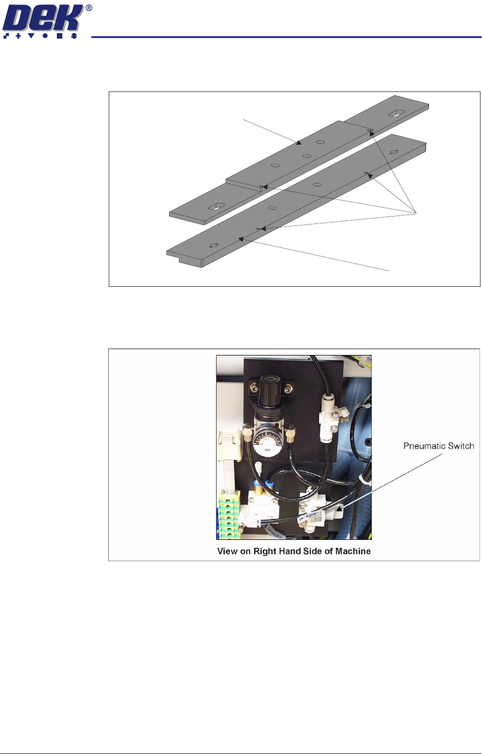
10. Turn the pneumatic switch Off, located on a magnetic plate on the right hand
side of the machine.
11. Under Setup select Machine.
12. Select Basic Parameters.
13. Set Clamp Type to Board Clamp.
14. This completes the procedure if board clamps have been fitted. If foil-less
clamps have been fitted continue with Step 15.
15. Load a product board.
16. In Diagnostics select Rail System.
17. Select Toggle Board clamp.
18. Using a 2mm Allen key adjust the two downstops on the rear foil-less clamp,
(previous figure refers) to ensure that the top of the foil-less clamp is flush
with the top of the board.
Downstops
Foil-less Clamp -
Adjustable Screen Mount (ASM)
Foil-less Clamp -
Fixed Width Chase
HIGH THROUGHPUT CONVEYOR (HTC) MODULE
REPLACEMENT PROCEDURES
17.38 Technical Reference Manual Chapter Issue 3 Oct 06
19. Repeat Step 18 for the front foil-less clamp.
20. Remove the board from the printer.
NOTE
The Board Clamp Setting procedure is not required after snugger to board
clamp/foil-less clamp replacement.
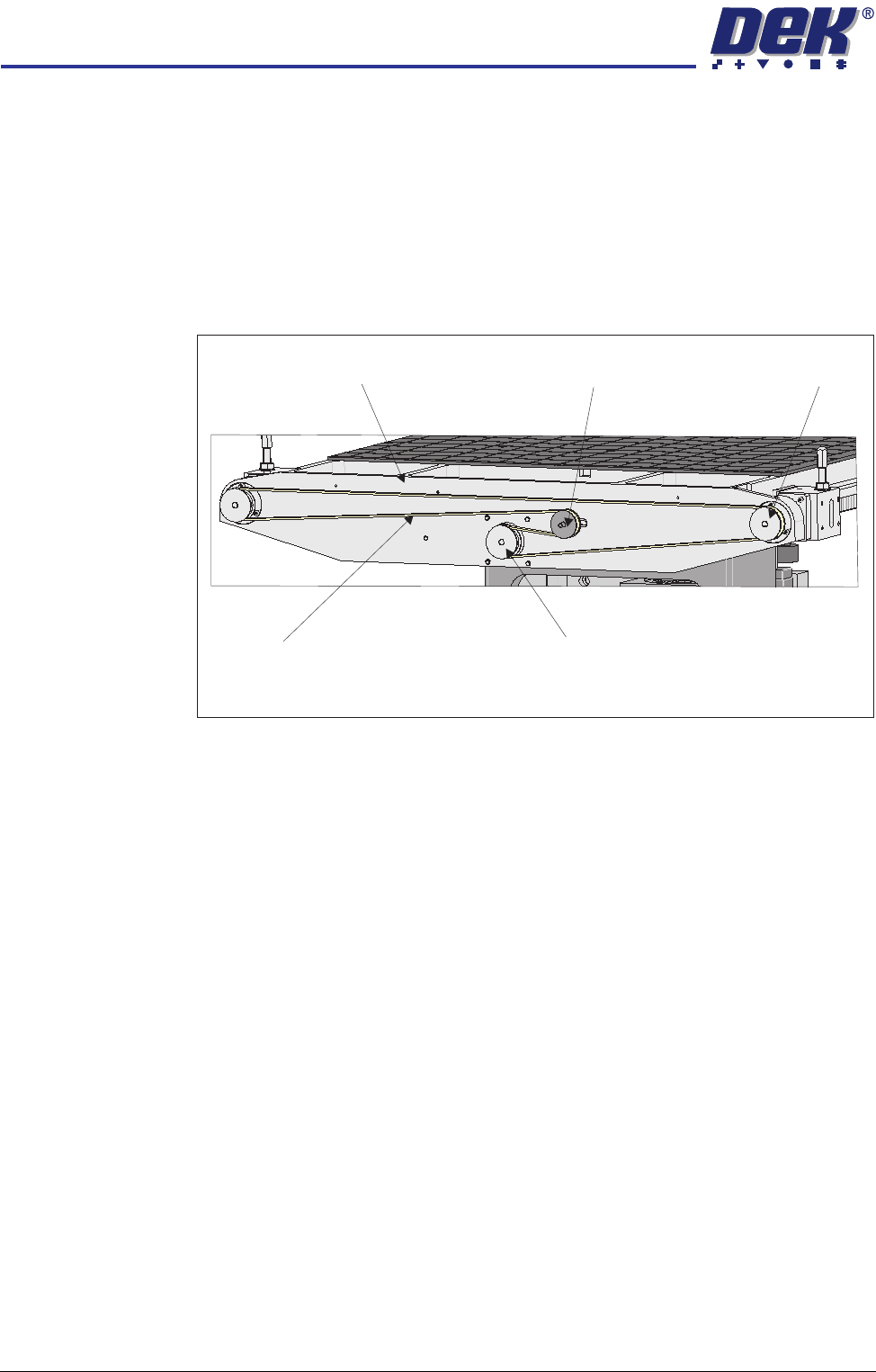
Rear Rail Drive Belt 1. At the rear of the rising table, slacken the adjustable idler pulley by means
of the nut at the front face of the rail drive plate.
2. Slide the adjustable idler pulley to slacken the drive belt.
3. Remove the drive belt and discard.
4. Fit the replacement drive belt.
5. Using a suitable cable tie, engage a forcemeter with the adjustable idler
pulley. Apply a horizontal force of 6kg.
6. Maintaining this force, tighten the adjustable idler pulley securing nut.
7. Using a tension meter on the top of the drive belt, check the tension is
between 38Hz - 45Hz.
8. Adjust the drive belt tension as necessary to achieve the reading in Step 7.
9. In Diagnostics select Rail System module.
10. Select Drive Rail Width Using Two Button Control.
11. Using the left jog button drive the rear rail to the rear for a few seconds, this
evens out the tension in the belt.
12. Repeat Steps 7-8.
13. Select Drive Rail to Board Width.
View on Rear of Rising Table
Adjustable Idler Pulley
Moving Rail Stepper Motor Pulley
Drive Belt
Left Hand Drive Shaft
Rail Drive Plate

HIGH THROUGHPUT CONVEYOR (HTC) MODULE
CALIBRATIONS
Chapter Issue 3 Oct 06 Technical Reference Manual 17.39
CALIBRATIONS
Board Transport
Belt Speed
(Auxiliary Rails)
The board transport belt speeds of the two auxiliary rails are controlled by the
M27 and are not adjustable. The belt speed can be measured using a
tachometer on the input or output pulley, check the speed to be approximately
30m/min.
Board Transport Belt Speed (Print Station Rail)
WARNING
LETHAL VOLTAGE. DANGEROUS VOLTAGES EXIST IN THIS EQUIPMENT.
ENSURE ALL ELECTRONIC COVERS AND MAIN MACHINE COVERS ARE
FITTED BEFORE OPERATING THIS EQUIPMENT.
The front and rear board transport belts, of the print station rail, are driven
independently by two variable speed motors. Inevitably one motor drives faster
than the other motor. It is necessary to calibrate these motors so that they drive
at the same speed in either direction. Therefore, the faster motor must be
calibrated to match the slower motors speed.
Each belt motor speed is controlled by a separate speed controller module
situated between the rails on the right hand side of the machine.
The belt speed is measured using a tachometer on the underside of the input
or output pulley and adjusted using the potentiometer on the speed controller
module.
Calibration
Procedure
1. In Diagnostics, select Rail System.
2. Select Belt Speed Calibration, the following window is displayed:
NOTE
Belt speed calibration figures displayed on this page have no relevance to
the belt speeds on this machine.
3. Select either Incr. or Decr. to start the belts.
Belt Speed Calibration
50000
50000
63999
63999
FRONT R TO L SPEED
FRONT L TO R SPEED
REAR L TO R SPEED
REAR R TO L SPEED