Printer 710_810 v8 High Throughput Conveyor Module.pdf - 第4页
HIGH THROUG HPUT CONVEY OR (HTC) MOD ULE OVERVIEW 17.4 Technical Reference Manual Chapter Issue 3 Oct 06 Board Clamping The transpor t rails can be fitt ed with one of the foll owing board cl amping arrangemen ts: • 250m…
HIGH THROUGHPUT CONVEYOR (HTC) MODULE
OVERVIEW
Chapter Issue 3 Oct 06 Technical Reference Manual 17.3
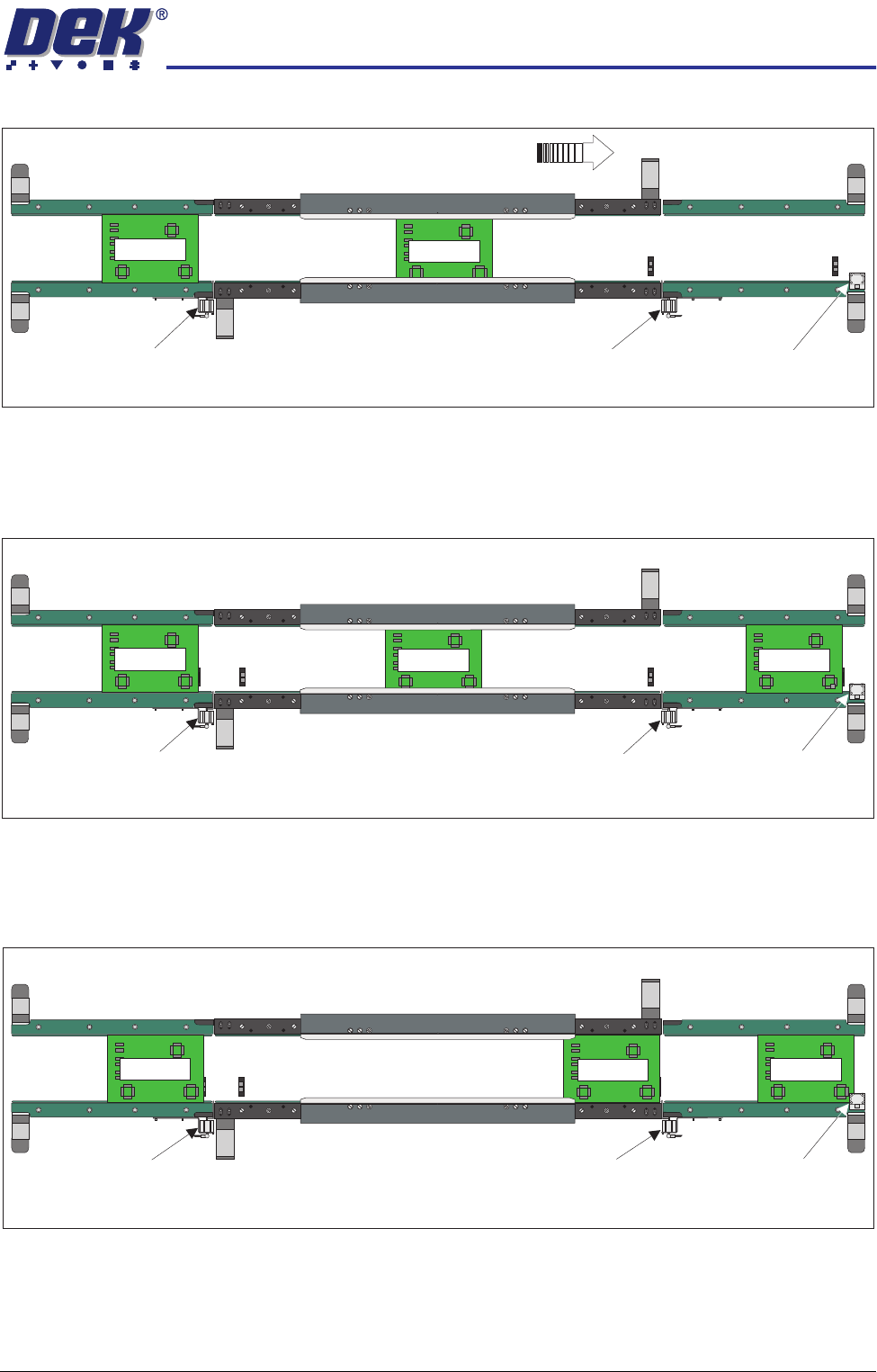
After the print cycle, the Board 1 is transported to the downline auxiliary
conveyor. When the leading edge of the board activates the sensor, at the end
of the downline auxiliary conveyor, a signal is sent allowing Board 2 to enter the
print station and Board 3 to enter on the upline auxiliary conveyor.
Providing the downline machine is ready, the first board can leave the downline
auxiliary conveyor and the cycle be repeated. If the downline machine is busy,
the second board is printed and transported to the end of the print station
conveyor where it is held by the conveyor board stop.
Three Stage Fast
Mode
In three stage fast mode, the operation is the same as three stage normal mode
with one exception. The second board is transported on to the print station
when the trailing edge of the first board passes the board at right opto situated
at the end of the print station conveyor.
KEYENCE
PZ-42L
K
E
Y
E
N
C
E
P
Z
-
4
2
L
Board 1
WARNING SHARP EDGE
PATENT No 5157438
WARNING SHARP EDGE
PATENT No 5157438
Print StationConveyor
Board Stop
Downline Conveyor
Board Stop
Upline Conveyor
Board Stop
Plan View of Board Positioning (Three Stage Mode)
Board Direction from Left to Right
KEYENCE
PZ-42L
K
E
Y
E
N
C
E
P
Z
-4
2
L
Board 2
KEYENCE
PZ-42L
KEYENCE
PZ-42L
KEYENCE
PZ-42L
K
E
Y
E
N
C
E
P
Z
-4
2
L
Board 2
WARNING SHARP EDGE
PATENT No 5157438
WARNING SHARP EDGE
PATENT No 5157438
Print StationConveyor
Board Stop
Downline Conveyor
Board Stop
Upline Conveyor
Board Stop
Plan View of Board Positioning (Three Stage Mode)
K
E
YE
N
C
E
P
Z
-
4
2
L
Board 1
K
E
Y
E
N
C
E
P
Z
-
4
2
L
Board 3
KEYENCE
PZ-42L
KEYENCE
PZ-42L
KEYENCE
PZ-42L
KEYENCE
PZ-42L
K
E
Y
E
N
C
E
P
Z
-
4
2
L
K
EY
E
N
C
E
P
Z
-4
2
L
K
E
Y
E
N
C
E
P
Z
-4
2
L
K
E
Y
E
N
C
E
P
Z
-
4
2
L
WARNING SHARP EDGE
PATENT No 5157438
WARNING SHARP EDGE
PATENT No 5157438
Print Station Conveyor
Board Stop
Downline Conveyor
Board Stop
Upline Conveyor
Board Stop
Plan View of Board Positioning (Three Stage Mode)
Board 3
Board 2
Board 1
KEYENCE
PZ-42L
HIGH THROUGHPUT CONVEYOR (HTC) MODULE
OVERVIEW
17.4 Technical Reference Manual Chapter Issue 3 Oct 06
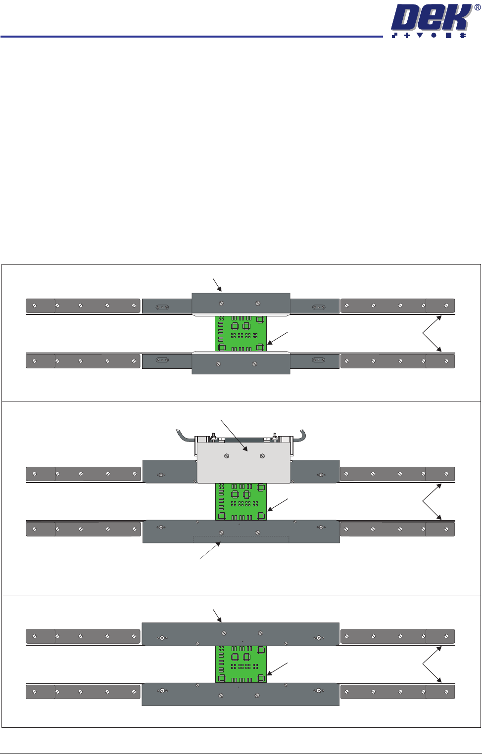
Board Clamping The transport rails can be fitted with one of the following board clamping
arrangements:
• 250mm Board Clamps
• 500mm Board Clamps
• Board Snugger Assembly
• Foil-less Clamps
Board snuggers are an alternative to the standard board clamps and are utilized
when there is a requirement to print close to the board edge.
Foil-less clamps are utilized for thin pliable boards where there is a requirement
to print close to the board edge. The foil-less clamps are assisted with the use
of a vacuum box beneath the product board.
Figure 17-1 Board Clamping Arrangements
Board
Transport Belts
Rear Snugger Plate
Counterweight Block
Board
Transport Belts
Rear Foil-less Clamp
Foil-less Clamps
Board
Transport Belts
Rear Board Clamp
Board Clamps
Board Snuggers
HIGH THROUGHPUT CONVEYOR (HTC) MODULE
ELECTRICAL SCHEMATIC
Chapter Issue 3 Oct 06 Technical Reference Manual 17.5
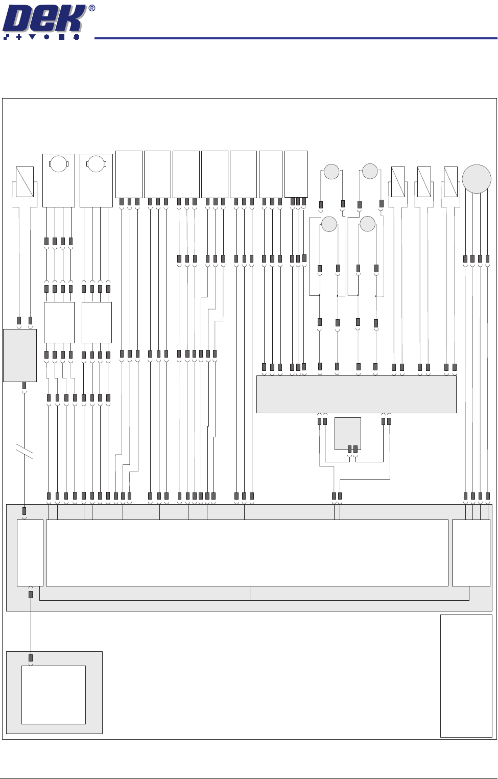
ELECTRICAL SCHEMATIC
3 Stage
(M27)
Conveyor
Controller
Machine PC
Motherboard
Machine Control Enclosure
DIG IN 10
DIG IN 11
DIG IN 6
Rail Lift Left
(8SE5)
Board at Right
Sensor (8SE7)
Board at Left
Sensor (8SE8)
8PL10
8PL117
M36PL17
8PL116
8PL12
Dual Stepper
X3
NextMove
Interface Card
X4
Front HTC Belt
Drive (M27M05)
M
8PL23
8PL22
Rear HTC Belt
Drive (M27M06)
M
Phase
Channel
+5V
GND
8PL21
M36PL18
!DIG OUT 3
DIG OUT 3
DIG OUT 2
DIG OUT 2
NextMove ES
(I/O Node 1)
X5
Main Machine
I/O Node 2
Board Clamp/
Snugger Solenoid
(16SOL10)
DIG OUT 9
GND
N2PL4
CAN Bus
N2SK2
USB
Moving Rail
Home (8SE6)
8PL26
M36PL19
DIG IN 5
DIG IN 7
Rail Lift Right
(8SE4)
+12V
8PL15
Sig
0V
NOTE
The breaks in the CAN Bus chain
reflect that additional I/O Nodes may
be fitted, refer to Machine Control
chapter for the complete CAN Bus
chain.
+12V
Sig
0V
+12V
Sig
0V
+12V
Sig
0V
+12V
Sig
0V
M36PL22
Moving Rail
Stepper
Motor 2B-
Motor 2A-
Motor 2B+
Motor 2A+
8PL20
8M2
+12V
Sig
0V
+12V
Sig
0V
Left Auxiliary
Rail Sensor
(27SE01)
Right Auxiliary
Rail Sensor
(27SE02)
M27PL05
M27PL14
M36PL04
M27PL02
M27PL01
M27PL03
M27PL11
Conveyor Board
Stop Solenoid
(M27SOL01)
Upline Board Stop
0V
M27PL08
Conveyor Board
Stop Solenoid
(M27SOL02)
Downline Board Stop
0V
M27PL20
Conveyor Board
Stop Solenoid
(M27SOL03)
Downline Board Stop
0V
M27PL21
Left Auxiliary Rail
Belt Drive
MIU
M01PL1
Speed
Controller
BGE 3004
M27SK24
M27PL26
Speed
Controller
BGE 3004
M27SK25
Phase
Channel
+5V
GND
Rear
(M27M04)
Rear
(M27M02)
M27PL17
M27PL07
Front
(M27M03)
Front
(M27M01)
Right Auxiliary Rail
Belt Drive
M27PL12
M27PL04
M27PL15
M27PL09
M
M
M
M
M27PL16
M27PL06