E4000-90023+N67xx+dut+ps+installation.pdf.pdf - 第10页
1-6 N67xx DUT Power Supply Installation Connecting the Output Cables These instructions ar e for a system being configur ed for the first time. 1 Wir e the connect or to the output cable. For N6751 and N6746, the cable m…
N67xx DUT Power Supply Installation 1-5
5 Connect the output cables to the ASRU Cards and DUT power supplies.
See Connecting the Output Cables on page 1-6.
6 To set up Fault/Inhibit system protection, see Setting Up Fault/Inhibit System
Protection on page 1-19.
7 Connect the power and GPIB cables as described in Connecting the Power and
GPIB Cables on page 1-25.
8 Update the system config file for the additional DUT power supply and verify
operation. See Updating the Configuration Files on page 1-28.
9 After verifying operation, install the covers on the DUT power supply racks.
1-6 N67xx DUT Power Supply Installation
Connecting the Output Cables
These instructions are for a system being configured for the first time.
1 Wire the connector to the output cable.
For N6751 and N6746, the cable must be secured with a strain relief.
2 Connect the output cables from the DUT power supply to the ASRU card. Refer
to the procedure for DUT power supply model you are installing.
– Connecting Output Cables for N6751
– Connecting Output Cables for N6752
– Connecting Output Cables for N6773
– Connecting Output Cables for N6746
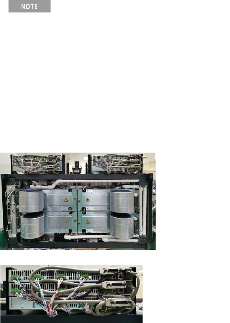
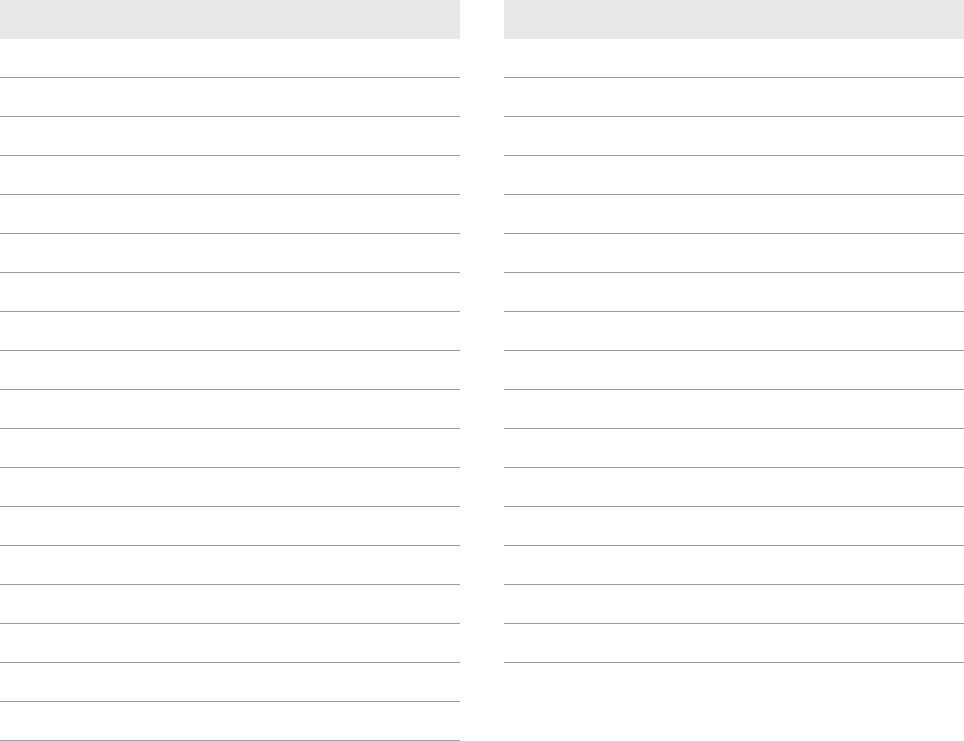
Figure 1-4 DUT power supplies (rear view of testhead in service position)
When adding a supply, the configuration of existing supplies
may prevent you from following all of these procedures.
Do not reconfigure existing supplies. Reconfiguring existing
supplies is likely to cause previously developed board tests to
fail.
N67xx DUT Power Supply Installation 1-7
Connecting Output Cables for N6751
The DUT power supply connections are J4 and J9 on the ASRU Card. The ASRU
Card end of the cable can be either a 34-pin connector or a 20-pin connector.
The 34-pin connector is for ASRU channels 1–4, and the 20-pin connector is for
channels 5–6. Refer to the Connector Wiring Charts and connect the output cables
as described in Connecting to the ASRU Card.
Connector Wiring Charts
• Connector A to J4 on ASRU Card
• Connector B to J9 on ASRU Card
Table 1-2 Connector A to J4 on ASRU Card
Pin Wire Color Wire Size Con/Terminal Pin Wire Color Wire Size Con/Terminal
1 VIO 24 F NC 19 NC
2 WHT 24 F NC 20 NC
3NC 21RED 24 H1
4 NC 22 WHT 24 H4
5 GRN 24 F1 23 WHT/GRN 24 G3
6 WHT 24 F4 24 WHT/GRN 24 G3
7 WHT/BRN 20 J3 25 WHT/BLU 20 G2
8 WHT/BRN 20 J3 26 WHT/BLU 20 G2
9 WHT/BLK 20 J2 27 NC
10 WHT/BLK 20 J2 28 NC
11 NC 29 BLK 24 J1
12 NC 30 WHT 24 J4
13 BLU 24 G1 31 BLK 20 F3
14 WHT 24 G4 32 BLK/WHT 20 F3
15 WHT/ORN 20 H3 33 RED 20 F2
16 WHT/ORN 20 H3 34 RED/WHT 20 F2
17 WHT/RED 20 H2
18 WHT/RED 20 H2