E4000-90023+N67xx+dut+ps+installation.pdf.pdf - 第17页
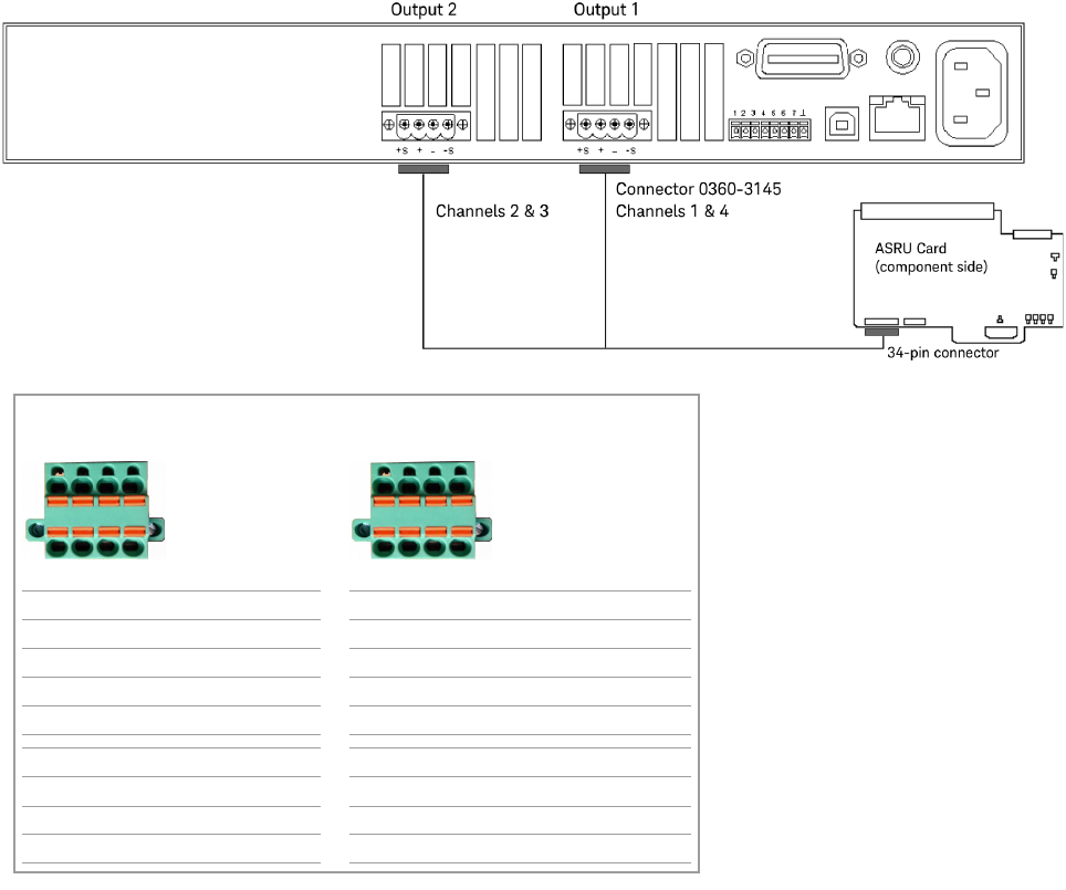
N67xx DUT Power Supply Installation 1-13 Figure 1-8 N6752 output connections – Channels 1 thr o ugh 4 Channel s 2 & 3 Channel s 1 & 4 P/S Label on cab le Cable color P /S Label on cable Cable color +S G1 BLU +S J…
1-12 N67xx DUT Power Supply Installation
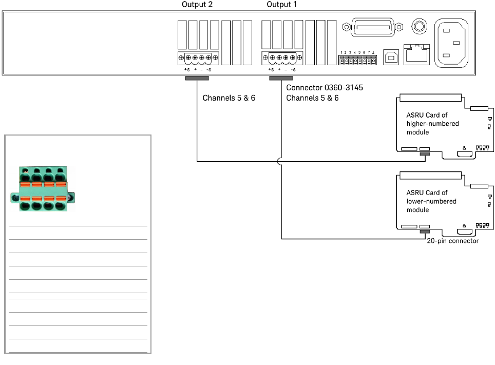
Figure 1-7 N6752 output connections – Channels 5 & 6
Channels 5 & 6
P/S Label on cable Cable color
+S K1 GRN
+ K2 BLK/WHT
– K3 BRN/WHT
–S K4 WHT
+S L1 BLU
+ L2 RED/WHT
– L3 ORN/WHT
–S L4 WHT
L1 L2 L3 L4
K1 K2 K3 K4
N67xx DUT Power Supply Installation 1-13
Figure 1-8 N6752 output connections – Channels 1 through 4
Channels 2 & 3 Channels 1 & 4
P/S Label on cable Cable color P/S Label on cable Cable color
+S G1 BLU +S J1 BLK
+ G2 BLU/WHT + J2 BLK/WHT
– G3 GRN/WHT – J3 BRN/WHT
–S G4 WHT –S J4 WHT
+S H1 RED +S F1 GRN
+ H2 RED/WHT + F2 RED, WHT/RED
– H3 ORN/WHT – F3 BLK, WHT/BLK
–S H4 WHT –S F4 WHT
G1 G2 G3 G4
H1 H2 H3 H4
F1 F2 F3 F4
J1 J2 J3 J4

1-14 N67xx DUT Power Supply Installation
Connecting to the Utility Card
The Utility Card provides an additional two channels of high current output
(channels 7–8). The power supply connector on the card is J601.
Table 1-4 Connector A to J601 on Utility Card
Pin Wire Color Wire Size Con/Terminal
1 VIO 24 CH7 S+
2 WHT 24 CH7 S–
3RED/BRN12
4BRN 12
5RED/ORN12
6ORN 12
7 BLK/BRN 12
8BLK 12
9 RED/BLK 12
10 RED 12
11 WHT 24 CH8 S–
12 GRN 24 CH8 S+
CH7 –
CH7 +
CH8 +
CH8 –