E4000-90023+N67xx+dut+ps+installation.pdf.pdf - 第22页
1-18 N67xx DUT Power Supply Installation Connecting Output Cables for N6746 Power fr om the N6746 power su pply can be r outed to any single mod ule, but must use either ASRU channel 5 or 6. It is r ecommended that you u…
N67xx DUT Power Supply Installation 1-17
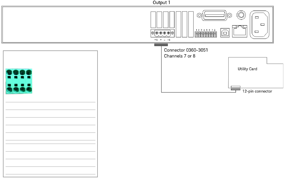
Connecting to the Utility Card
The N6773 DUT Power Supply can be connected to channel 7 or 8 on the Utility
Card as shown Figure 1-11.
Figure 1-11 N6773 output connections – Channels 7 or 8 (Utility Card)
Channel 7 or 8
P/S Label on cable Cable color
+S CH7 S+ VIO
+ CH7 + RED/ORN, ORN
– CH7 - RED/BRN, BRN
–S CH7 S- WHT
+S CH8 S+ GRN
+ CH8 + BLK/BRN, BLK
– CH8 - RED/BLK, RED
–S CH8 S- WHT
+–
S
+
+–
S
–
1-18 N67xx DUT Power Supply Installation
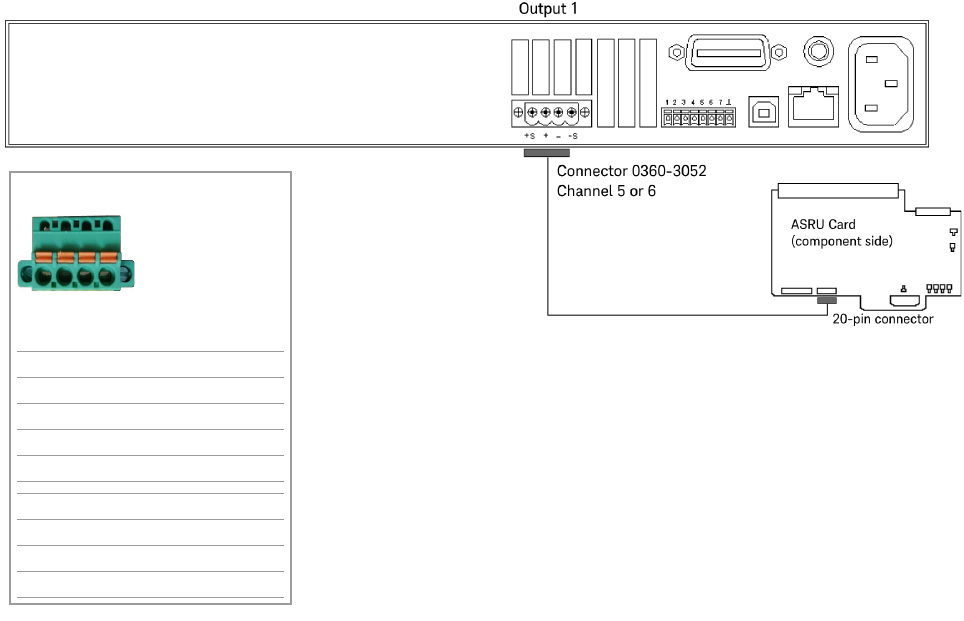
Connecting Output Cables for N6746
Power from the N6746 power supply can be routed to any single module, but must
use either ASRU channel 5 or 6. It is recommended that you use ASRU channel 6
as a first choice when configuring this supply. Up to four power outputs can be
routed to any single module or they can be split across four modules. (Each output
powers one module.)
Connect the output cables as shown in Figure 1-12.
Figure 1-12 N6746 output connections
Channel 5 or 6
P/S Label on cable Cable color
+S L1 BLU
+ L2 RED/WHT
– L3 ORN/WHT
–S L4 WHT
+S K1 GRN
+ K2 BLK/WHT
– K3 BRN/WHT
–S K4 WHT
L1 L2 L3 L4
K1 K2 K3 K4
or
N67xx DUT Power Supply Installation 1-19
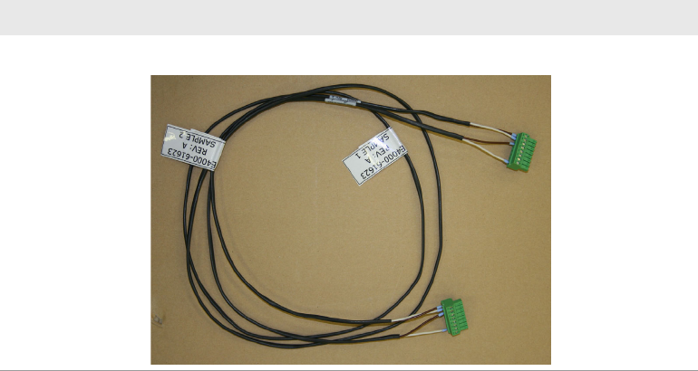
Setting Up Fault/Inhibit System Protection
To set up Fault/Inhibit system protection, an OVL sense cable is required. Refer to
the following sections:
• Digital Control Port
• What is Being Connected in ICT?
Table 1-5 OVL sense cable
Part number Description
03066-61623 OVL sense cable, 67xx DUT power supply