E4000-90023+N67xx+dut+ps+installation.pdf.pdf - 第23页
N67xx DUT Power Supply Installation 1-19 Setting Up Fault/Inhi bit System Protection To set up Fault/Inhibit system pr otection, an OVL sens e cable is r equir ed. Refer to the following sections: • Digital Control Port …
1-18 N67xx DUT Power Supply Installation
Connecting Output Cables for N6746
Power from the N6746 power supply can be routed to any single module, but must
use either ASRU channel 5 or 6. It is recommended that you use ASRU channel 6
as a first choice when configuring this supply. Up to four power outputs can be
routed to any single module or they can be split across four modules. (Each output
powers one module.)
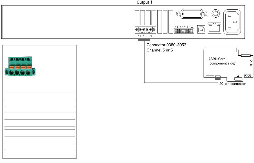
Connect the output cables as shown in Figure 1-12.
Figure 1-12 N6746 output connections
Channel 5 or 6
P/S Label on cable Cable color
+S L1 BLU
+ L2 RED/WHT
– L3 ORN/WHT
–S L4 WHT
+S K1 GRN
+ K2 BLK/WHT
– K3 BRN/WHT
–S K4 WHT
L1 L2 L3 L4
K1 K2 K3 K4
or
N67xx DUT Power Supply Installation 1-19
Setting Up Fault/Inhibit System Protection
To set up Fault/Inhibit system protection, an OVL sense cable is required. Refer to
the following sections:
• Digital Control Port
• What is Being Connected in ICT?
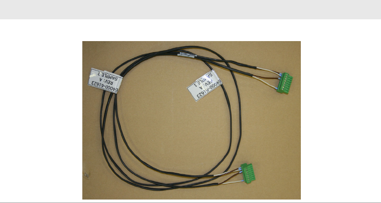
Table 1-5 OVL sense cable
Part number Description
03066-61623 OVL sense cable, 67xx DUT power supply
1-20 N67xx DUT Power Supply Installation
Digital Control Port
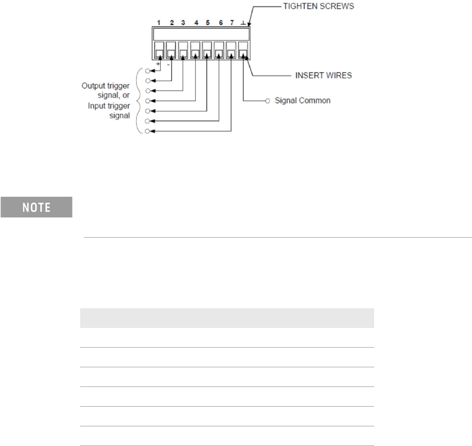
An 8-pin connector and a quick-disconnect connector plug are provided for
accessing the digital control port functions.
The digital control connector accepts wires sizes from AWG 14 to AWG 30. Note
that wire sizes smaller than AWG 24 are not recommended. Disconnect the
connector plug to make your wire connections.
The following chart describes the possible pin configuration for the digital port
functions.
In addition to the configurable pin functions, the active signal polarity for each pin
is also configurable. When Positive polarity is selected, a logical true signal is a
voltage high at the pin. When Negative polarity is selected, a logical true signal is
a voltage low at the pin.
It is good engineering practice to twist and shield all signal wires to and from the
digital connectors. If shielded wire is used, connect only one end of the shield to
chassis ground to prevent ground loops.
Table 1-6 Pin configuration
Pin function Availablel configurable pins
Digital I/O and Digital In Pins 1 through 7
External Trigger In/Out Pins 1 through 7
Fault Out Pins 1 and 2
Inhibit In Pin 3
Output State Pins 4 through 7
Common (⊥)Pin 8