E4000-90023+N67xx+dut+ps+installation.pdf.pdf - 第26页
1-22 N67xx DUT Power Supply Installation Inhibit Input Pin 3 can be configur ed as a r emote inhibit input. The pola rity of pin 3 can also be configur ed. Pin 8 is the common for pin 3. The Inhibit Input function lets a…
N67xx DUT Power Supply Installation 1-21
What is Being Connected in ICT?
• Fault Output
• Inhibit Input
• Fault/Inhibit System Protection
• Clearing a System Protection Fault
Fault Output
Pins 1 and 2 can be configured as a fault-output pair. The polarity of pin 1 can also
be configured. Pin 1 is the Fault output; pin 2 is the common for pin 1. Note that
pin 2 must also be connected to pin 8.
The Fault output function enables a fault condition on any channel to generate a
fault signal on the digital control port. The following conditions will generate a fault
event: over-voltage, over-current, over-temperature, inhibit signal, power-fail
condition, or on some models, a power-limit condition.
Both pins 1 and 2 are dedicated to this function. This provides for an
optically-isolated output. Pin 2’s function is ignored.
Note that the Fault output signal remains latched until the fault condition is
cleared. You must also clear the protection circuit.
From the front panel:
1 Select System\IO\DigPort\Pins.
2 Select pin 1, then Function, then Fault Out.
3 In the Polarity field, select either Positive or Negative.
Using SCPI commands:
To configure the Fault function:
DIG:PIN1:FUNC FAUL
To select the fault output polarity:
DIG:PIN1:POL<pol>

1-22 N67xx DUT Power Supply Installation
Inhibit Input
Pin 3 can be configured as a remote inhibit input. The polarity of pin 3 can also be
configured. Pin 8 is the common for pin 3.
The Inhibit Input function lets an external input signal control the output state of all
the output channels in the DUT power supply. The signal latency is 5 microseconds.
Pin 3 can be programmed for the following Inhibit modes, which are stored in
non-volatile memory:
From the front panel:
1 Select System\IO\DigPort\Pins.
2 Select pin 3, then Function, then Inhibit In.
3 In the Polarity field, select either Positive or Negative.
4 Select Protect\Inhibit.
5 Select either Latching or Live.
6 To disable the Inhibit signal, select Off.
Using SCPI commands:
To configure the Inhibit function:
DIG:PIN3:FUNC INH
To select the inhibit input polarity:
DIG:PIN3:POL <pol>
To latch the Inhibit signal:
OUTP:INH:MODE LATC
To set the Inhibit signal live:
OUTP:INH:MODE LIVE
To disable the Inhibit signal:
OUTP:INH:MODE OFF
Table 1-7 Inhibit modes
Mode Description
LATChing Causes a logic-true transition on the Inhibit input to disable all outputs. The
outputs will remain disabled after the inhibit signal is received.
LIVE Allows the enabled outputs to follow the state of the Inhibit input. When the
Inhibit input is true, the outputs are disabled. When the Inhibit input is false, the
outputs are re-enabled.
OFF The Inhibit input is ignored.
N67xx DUT Power Supply Installation 1-23
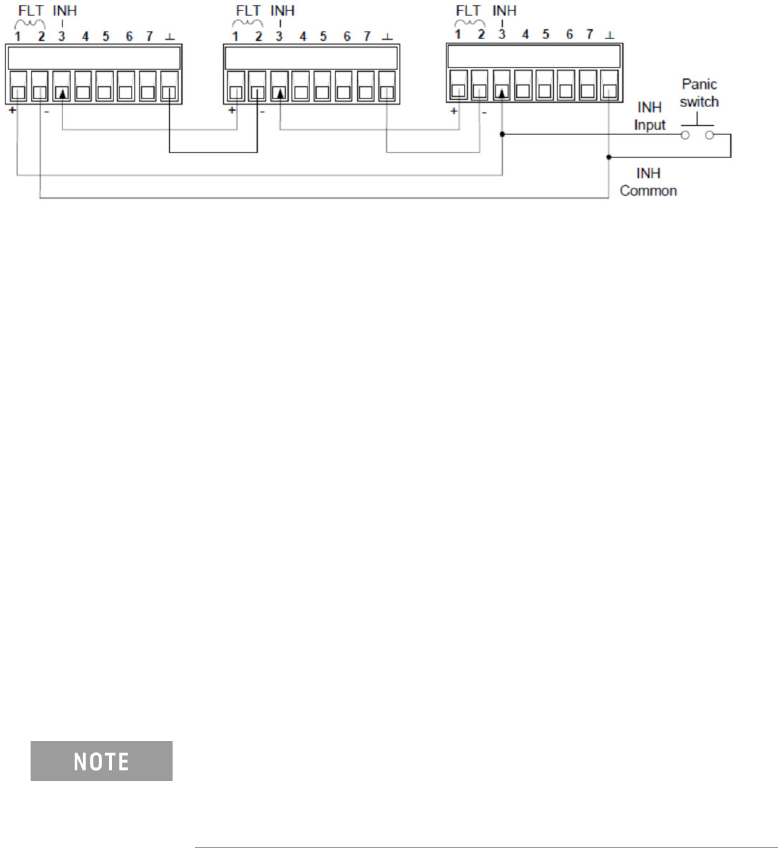
Fault/Inhibit System Protection
The following figure illustrates some ways that you can connect the Fault/Inhibit
pins of the connector.
As shown above, when the Fault outputs and Inhibit inputs of several DUT power
supplies are daisy-chained, an internal fault condition in one of the DUT power
supplies will disable all of them without intervention by either the controller or
external circuitry.
You can also connect the Inhibit input to a manual switch or external control signal
that will short the Inhibit pin to common whenever it is necessary to disable all
output channels in the DUT power supply. Negative polarity must be programmed
for all pins in this case. You can also use the Fault output to drive an external relay
circuit or signal other devices whenever a user-definable fault occurs.
Clearing a System Protection Fault
If an over-voltage, over-current, over-temperature, power-fail condition,
power-limit condition, protection condition, or inhibit signal occurs, the power
system turns off the affected output channel. The appropriate operating status
indicator on the front panel will be on.
To clear the protection function and restore normal operation, first remove that
condition that caused the protection fault. Then, clear the protection function.
To clear the daisy-chained fault signal if the operating mode of the Inhibit input is
Live, simply clear the output protection on any ONE DUT power supply as described
below. If the operating mode of the Inhibit input is Latched, turn off the Inhibit input
on ALL DUT power supplies individually. To re-enable the chain, re-program the
Inhibit input on each DUT power supply to Latched mode.
Even when the initial fault condition or external signal is
removed, the Inhibit fault signal is still active and will
continue to shut down the outputs of all the DUT power
supplies.