E4000-90023+N67xx+dut+ps+installation.pdf.pdf - 第5页
Keysight i3070 In-Circuit Test System N67xx DUT Power Supply Installation N67xx DUT Power Supply Overview 1-2 Instal ling the DU T Power Supply 1-4 Connecting the Output Cables 1-6 Setting Up Faul t/Inhibit System Protec…
iv

Keysight i3070 In-Circuit Test System
N67xx DUT Power Supply Installation
N67xx DUT Power Supply
Overview 1-2
Installing the DUT Power Supply 1-4
Connecting the Output Cables 1-6
Setting Up Fault/Inhibit System Protection 1-19
Connecting the Power and GPIB Cables 1-25
Updating the Configuration Files 1-28
Verifying Operation 1-30
This guide describes the installation of the N67xx DUT power supplies in the i3070
Series 6 test systems (2- or 4-module).
The procedures in this document must be performed by
personnel who are trained and qualified to service Keysight
systems.
1-2 N67xx DUT Power Supply Installation
Overview
The DUT power supplies are installed in the rack(s) behind the i3070 Series 6
testhead.
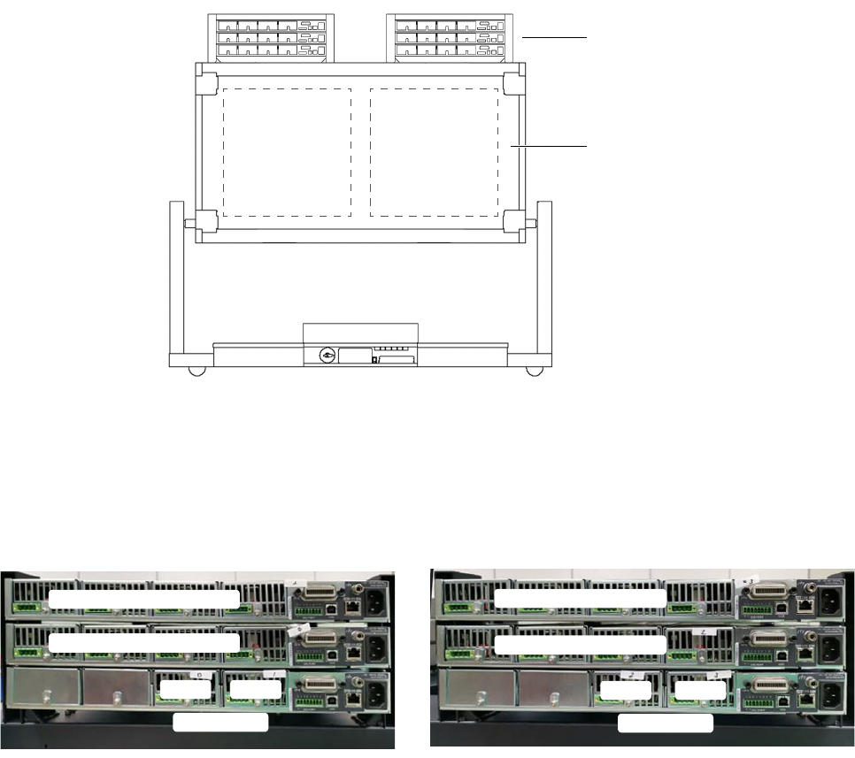
Figure 1-1 shows the location of DUT power supplies in a 4-module system (rear
view, service position). A 2-module system contains only Bank 2 and one rack for
the DUT power supplies. The same installation instructions apply.
Figure 1-1 DUT power supplies in 4-module system
Install the DUT power supplies in the outer slot first, followed by the middle slot and
lastly the inner slot.
Figure 1-2 Assembly sequence of DUT power supplies
DUT power supplies
testhead
Bank 1 Bank 2
Above Bank 2
Module 3 Channel 1–4
Mod ule 1 Channel 1–4
Mod ule 3 Channel 1–4
Mod ule 2 Channel 1–4
Mod 2
Channel 5–6
Mod 3
Mod ule 0 Channel 1–4
Mod 2
Channel 5–6
Mod 3
Above Bank 1