E4000-90023+N67xx+dut+ps+installation.pdf.pdf - 第7页
N67xx DUT Power Supply Installation 1-3 Part Numbers Tool s Needed • T20 Torx driver – for r ear covers and DUT power supply covers • #2 Pozidriv scr ewdriver, or offset or ra tchet scr ewdriver – for DUT power supply br…
1-2 N67xx DUT Power Supply Installation
Overview
The DUT power supplies are installed in the rack(s) behind the i3070 Series 6
testhead.
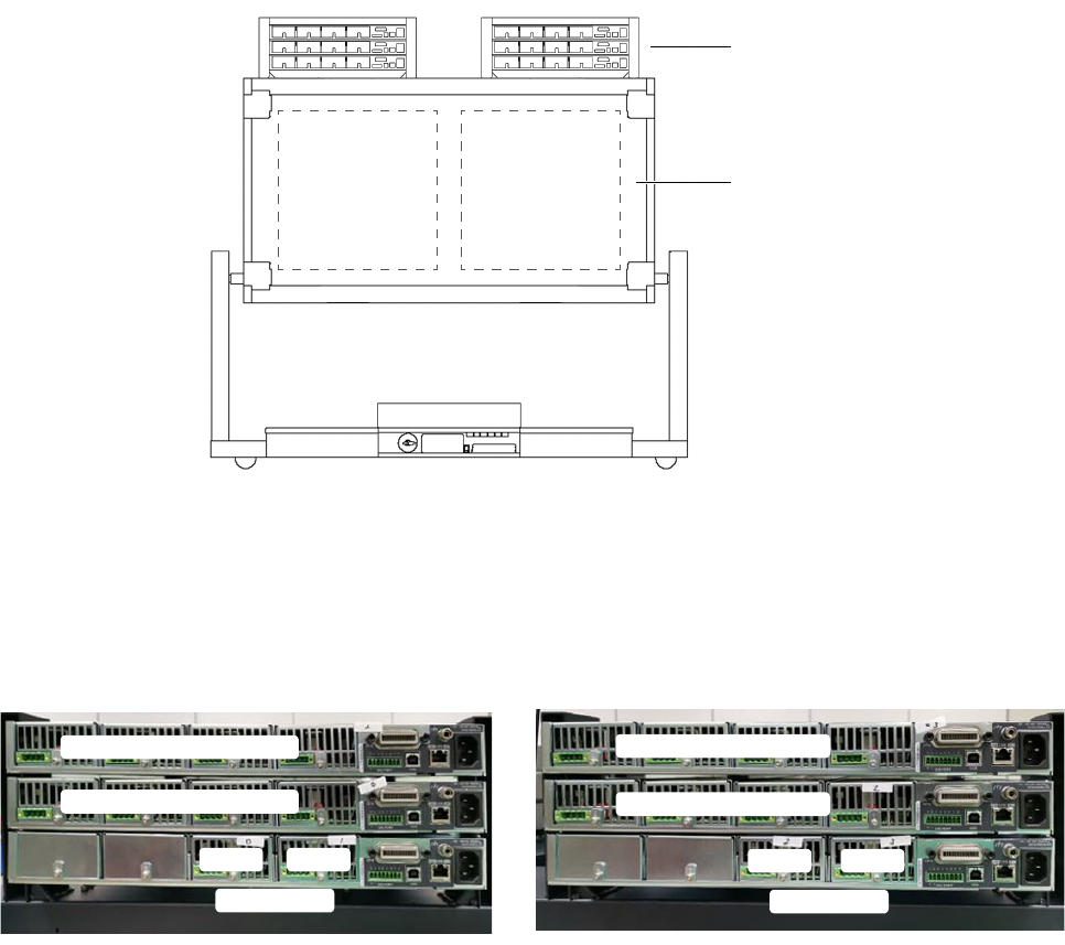
Figure 1-1 shows the location of DUT power supplies in a 4-module system (rear
view, service position). A 2-module system contains only Bank 2 and one rack for
the DUT power supplies. The same installation instructions apply.
Figure 1-1 DUT power supplies in 4-module system
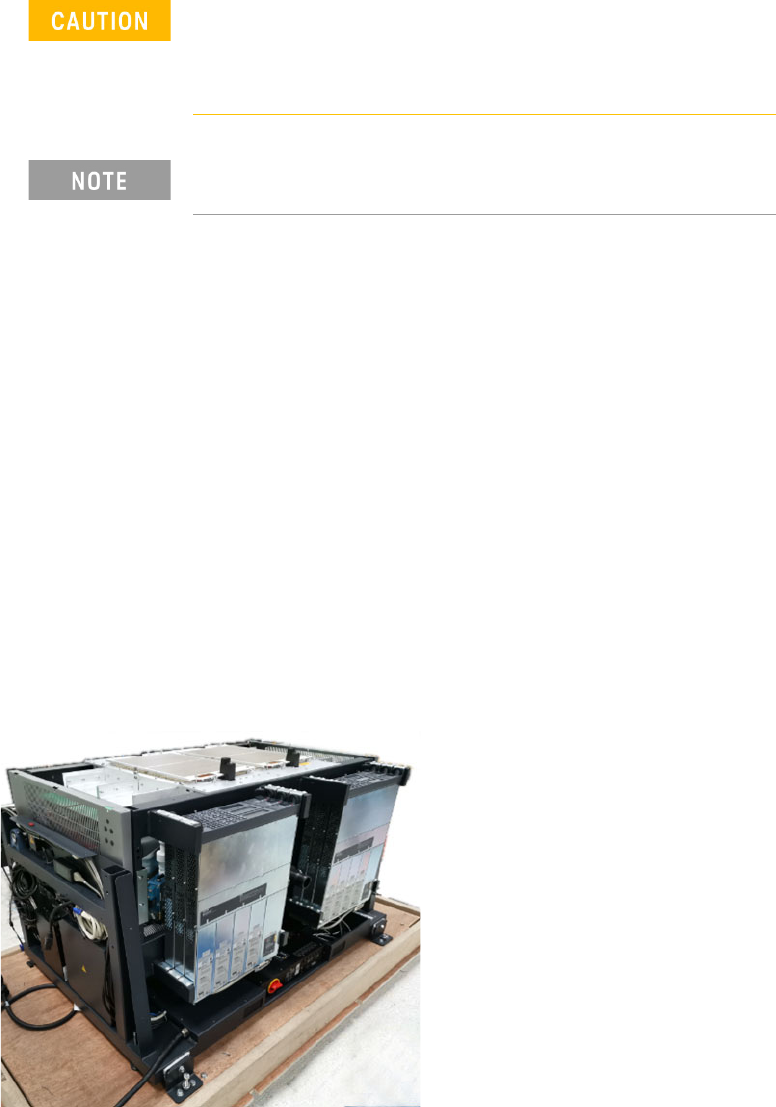
Install the DUT power supplies in the outer slot first, followed by the middle slot and
lastly the inner slot.
Figure 1-2 Assembly sequence of DUT power supplies
DUT power supplies
testhead
Bank 1 Bank 2
Above Bank 2
Module 3 Channel 1–4
Mod ule 1 Channel 1–4
Mod ule 3 Channel 1–4
Mod ule 2 Channel 1–4
Mod 2
Channel 5–6
Mod 3
Mod ule 0 Channel 1–4
Mod 2
Channel 5–6
Mod 3
Above Bank 1

N67xx DUT Power Supply Installation 1-3
Part Numbers
Tools Needed
• T20 Torx driver – for rear covers and DUT power supply covers
• #2 Pozidriv screwdriver, or offset or ratchet screwdriver – for DUT power
supply brackets
• T10 Torx driver – for DUT power supply brackets
Table 1-1 For DUT power supply installation
Part Number Description Quantity
Brackets
N1808-01212 Bracket, DUTPS - Rear 12
N1808-01217 Bracket, DUTPS - Front 12
E9900-06001 Screw 48
(A pair of front brackets and a pair of rear brackets
required for each DUT power supply.)
Cables
N1807-61622 Module Cable 4 Channel; Short N67xx DUTPS, S6 1
N1807-61623 Mod Activation N67xx DUTPS Cable 2CH, S6 1
(One of each cable for every module activated.
N1807-61623 is used for Channel 5–6.)
Covers
N1808-01214 Front Cover, DUTPS Series 6 2
N1808-01213 Cover, DUTPS Series 6 2
E9900-04124 Rear Cover E9902G/03G - Middle 1
1-4 N67xx DUT Power Supply Installation
Installing the DUT Power Supply
Inventory the DUT power supply kit. Compare the part numbers and quantities of
parts to the Parts List in the kit. Report any discrepancies to your Keysight support
representative.
1 Preparation:
a Remove any test fixture that may be on the system.
b Run Diagnostics, especially the DUT power supply tests, with a pin
verification fixture. Correct any problems before installing the DUT supply.
c Turn power to the testhead OFF:
Execute
testhead power off and switch the system PDU OFF.
2 Install the two front brackets and two rear brackets on the power supply.
3 Slide the power supply into the rack (starting with the outer slot).
4 Secure the front brackets to the front of the rack, then secure the rear
brackets.
Figure 1-3 Install DUT power supplies
Before beginning the installation procedures, power to the
testhead must be turned OFF.
The system must be shut down, but the controller may remain
active for use by programmers.
Universal AC input - DUT power supplies have universal input
voltage capability with active power factor correction.