E4000-90023+N67xx+dut+ps+installation.pdf.pdf - 第9页
N67xx DUT Power Supply Installation 1-5 5 Connect the output cables to the ASRU Car ds and DUT power su pplies. See Connectin g the Output Cables on page 1-6. 6 To set up Faul t/Inhibit system pr otection, see Setting Up…
1-4 N67xx DUT Power Supply Installation
Installing the DUT Power Supply
Inventory the DUT power supply kit. Compare the part numbers and quantities of
parts to the Parts List in the kit. Report any discrepancies to your Keysight support
representative.
1 Preparation:
a Remove any test fixture that may be on the system.
b Run Diagnostics, especially the DUT power supply tests, with a pin
verification fixture. Correct any problems before installing the DUT supply.
c Turn power to the testhead OFF:
Execute
testhead power off and switch the system PDU OFF.
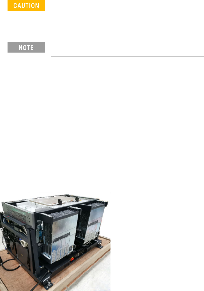
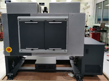
2 Install the two front brackets and two rear brackets on the power supply.
3 Slide the power supply into the rack (starting with the outer slot).
4 Secure the front brackets to the front of the rack, then secure the rear
brackets.
Figure 1-3 Install DUT power supplies
Before beginning the installation procedures, power to the
testhead must be turned OFF.
The system must be shut down, but the controller may remain
active for use by programmers.
Universal AC input - DUT power supplies have universal input
voltage capability with active power factor correction.
N67xx DUT Power Supply Installation 1-5
5 Connect the output cables to the ASRU Cards and DUT power supplies.
See Connecting the Output Cables on page 1-6.
6 To set up Fault/Inhibit system protection, see Setting Up Fault/Inhibit System
Protection on page 1-19.
7 Connect the power and GPIB cables as described in Connecting the Power and
GPIB Cables on page 1-25.
8 Update the system config file for the additional DUT power supply and verify
operation. See Updating the Configuration Files on page 1-28.
9 After verifying operation, install the covers on the DUT power supply racks.
1-6 N67xx DUT Power Supply Installation
Connecting the Output Cables
These instructions are for a system being configured for the first time.
1 Wire the connector to the output cable.
For N6751 and N6746, the cable must be secured with a strain relief.
2 Connect the output cables from the DUT power supply to the ASRU card. Refer
to the procedure for DUT power supply model you are installing.
– Connecting Output Cables for N6751
– Connecting Output Cables for N6752
– Connecting Output Cables for N6773
– Connecting Output Cables for N6746
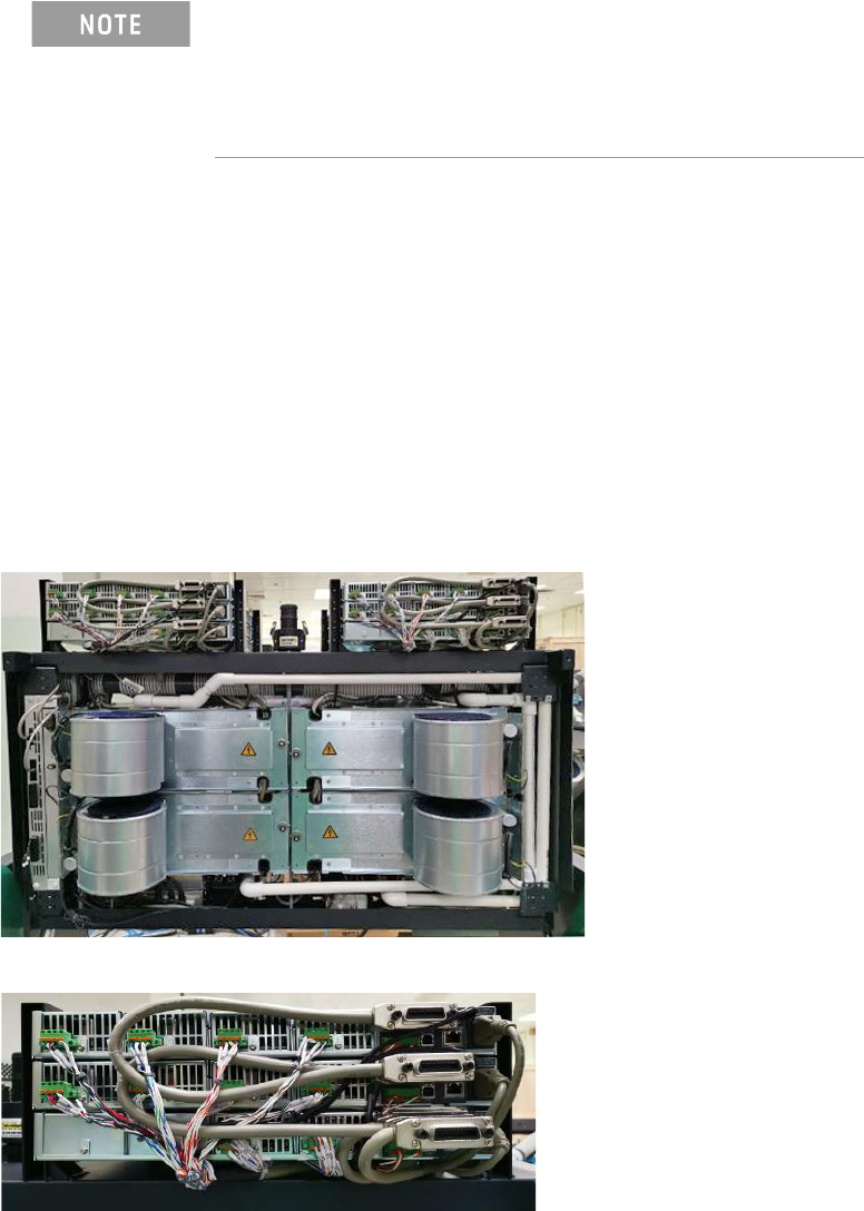
Figure 1-4 DUT power supplies (rear view of testhead in service position)
When adding a supply, the configuration of existing supplies
may prevent you from following all of these procedures.
Do not reconfigure existing supplies. Reconfiguring existing
supplies is likely to cause previously developed board tests to
fail.