00192402-01.pdf - 第14页
GEM for SIPLACE V7.01 Page 14 of 251 ©Siem ens AG, all rights reserved (TXLSPHQW The SIPLACE 80S-20 or SIPLACE 80F 4 with GEM/SECS II-Interface 2SHUDWRU The pers on who phy sically has access to the equipm ent ’ s m ater…
GEM for SIPLACE V7.01
©Siemens AG, all rights reserved page 13 of 251
1.4 *(0&RPSOLDQFH6WDWHPHQW
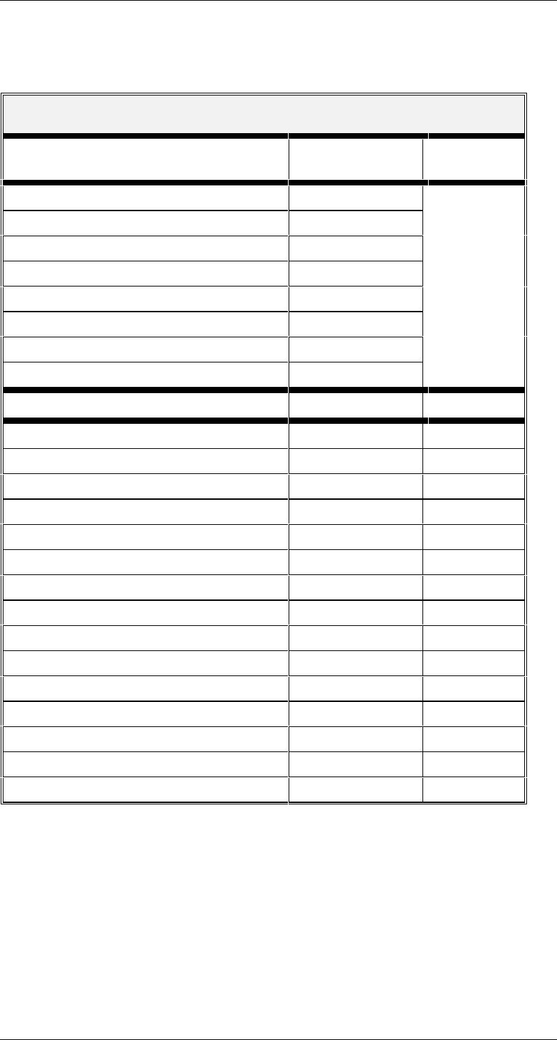
GEM COMPLIANCE STATEMENT
FUNDAMENTAL GEM REQUIREMENTS IMPLEMENTED
COMPLIANT
State Models ✓ Yes ¨ No
Equipment Processing States ✓ Yes ¨ No ✓ Yes
S1,F13/F14 Scenario ✓ Yes ¨ No
Event Notification ✓ Yes ¨ No
On-line Identification ✓ Yes ¨ No
Error Messages ✓ Yes ¨ No ¨ No
Control (Operator Initiated) ✓ Yes ¨ No
Documentation ✓ Yes ¨ No
ADDITIONAL CAPABILITIES IMPLEMENTED COMPLIANT
Establish Communications ✓ Yes ¨ No ✓ Yes ¨ No
Dynamic Event Report Configuration ✓ Yes ¨ No ✓ Yes ¨ No
Variable Data Collection ✓ Yes ¨ No ✓ Yes ¨ No
Trace Data Collection ✓ Yes ¨ No ✓ Yes ¨ No
Status Data Collection ✓ Yes ¨ No ✓ Yes ¨ No
Alarm Management ✓ Yes ¨ No ✓ Yes ¨ No
Remote Control ✓ Yes ¨ No ✓ Yes ¨ No
Equipment Constants ✓ Yes ¨ No ✓ Yes ¨ No
Process Program Management * ✓ Yes ¨ No ✓ Yes ¨ No
Material Movement ✓ Yes ¨ No ✓ Yes ¨ No
Equipment Terminal Services ✓ Yes ¨ No ✓ Yes ¨ No
Clock ✓ Yes ¨ No ✓ Yes ¨ No
Limits Monitoring ✓ Yes ¨ No ✓ Yes ¨ No
Spooling ✓ Yes ¨ No ✓ Yes ¨ No
Control (Host Initiated) ✓ Yes ¨ No ✓ Yes ¨ No
* is only possible to have one program on the SIPLACE (the GEM standard requires
three)
7HUPLQRORJ\
The following terms are used throughout the document to refer to the various entities
interfacing with the SIPLACE:

GEM for SIPLACE V7.01
Page 14 of 251 ©Siemens AG, all rights reserved
(TXLSPHQW The SIPLACE 80S-20 or SIPLACE 80F
4
with GEM/SECS II-Interface
2SHUDWRU The person who physically has access to the equipment’s material port(s)
and control panel. This is the person who is operating the SIPLACE.
+RVW The computer which is connected to the equipment via the SECSII-interface
6WDWH'LDJUDPV
This document uses several )LQLWH6WDWH0DFKLQH diagrams to describe the current
condition of the Equipment’s SECS link, material handling mechanisms, and process
cycle. Each Finite State Machine diagram includes a State Diagram and a complete
description of the states and state transitions.
All Finite State Diagrams have been prepared in the format specified in the GEM
standard. This notation is required as a fundamental part of GEM compliance and must
be included in the Equipment SECS Interface Documentation. This notation is the
„Statechart“ notation developed by David Harel.
The following are the major characteristics of this notation as it is used in this document:
Each state is represented by a rectangle with rounded corners.
A collection of sub-states may be grouped into a super-state.
The entity described by the diagrams will be in one and only one of the sub-states at all
times.
Variables representing the current state of an entity do not contain values for super-
states, only the lowest sub-state is represented.
State transitions are represented by single-headed arrows.
Each state transition is a Collection Event, and it has a unique Collection Event ID (CEID)
An arrow directly from a super-state to another state describes a Collection Event that can
occur while the entity is in any one of the sub-states contained in the super-state.
An arrow directly into a super-state to the + (history) symbol describes a transition to the
lowest sub-state which described the entity just before the transition out of the super-
state.
An arrow directly into a super-state to the & (conditional) symbol describes a transition to
a particular sub-state based on some other relevant data. The conditional data is not
represented in the diagram but is described in the associated text.
GEM for SIPLACE V7.01
©Siemens AG, all rights reserved page 15 of 251
0HVVDJH6XPPDU\
+RVWWR(TXLSPHQW
This section describes primary SECS messages sent by the Host, and the associated
reply messages from the Equipment.
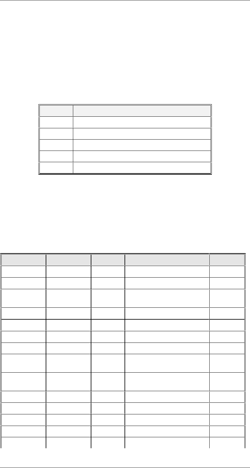
The column headed "CState" in the table below indicates the control state the Equipment
must be in to accept the message. The current value of the Equipment Control State can
be found in variable CONTROLSTATE (vid 1002006). Possible values for this column are
as follows:
Value State
1 Off-Line/Equipment Off-Line
2 Off-Line/Attempt On-Line
3 Off-Line/Host Off-Line
4 On-Line/Local
5 On-Line/Remote
Unlawful messages sent to the Equipment while Control State is Off-Line (1, 2, or 3) will
be replied to with a SnF0 message. Thus, the Host will only ever see values of 4 or 5 for
CONTROLSTATE.
In the column headed "Notes", those messages marked with "E" are extensions beyond
GEM. Those messages marked with "N" are provided for non-GEM or older GEM
compatibility.
Primary Reply CState Description Notes
S1F1 S1F2 4,5 Are You There
S1F3 S1F4 4,5 Selected Status
S1F11 S1F12 4,5 Status Variable Namelist
Request
S1F13 S1F14 All Connect Request
S1F15 S1F16 4,5 Request Off-Line
S1F17 S1F18 1,2,3 Request On-Line
S1F65 S1F66 All Connect Request N
S2F13 S2F14 4,5 Equipment Constant
Request
S2F15 S2F16 4,5 New Equipment Constant
Send
S2F17 S2F18 4,5 Date and Time Request
S2F21 S2F22 5 Remote Command N
S2F23 S2F24 4,5 Trace Initialize
S2F25 S2F26 4,5 Loopback Diagnostic E
S2F27 S2F28 5 Initiate Processing N