00192402-01.pdf - 第22页
GEM for SIPLACE V7.01 Page 22 of 251 ©Siem ens AG, all rights reserved 5HODWHG9DULDEOHV The f ollowing table lists the variables ( SV's, EC's, or DVVALS) which are relevant to establishing com m unicati…

GEM for SIPLACE V7.01
©Siemens AG, all rights reserved page 21 of 251
&RPPXQLFDWLRQ6WDWHV
The current Communication State will be one of the following values. There is no Variable
indicating the Communication State. The communication State is presented to the
Operator on the main Operator Interface screen.
',6$%/('
The SECS link to the Host is disabled at the SIPLACE. The Equipment will send no
messages to the Host. The Equipment will not respond to a Host-initiated ENQ.
(1$%/('
When communications are Enabled, the Equipment's intention is to be in communication
with the Host. Whether or no the SIPLACE is currently communicating with the Host
determines which sub-state of the Enabled super-state the SIPLACE is in.
&20081,&$7,1*
The SECS link between the SIPLACE and the Host is operating normally.
Periodically, the Equipment will send a "Heartbeat" message S1F1 to ensure that the link
is still operating. The heartbeat frequency is controlled by Equipment Constant
HEARTBEAT. HEARTBEAT (VID 1002055) can range from 0 to 32000, with default
value 30.
If the Equipment encounters a SECS-I Retry Limit (RTY) error when attempting to send a
block to the Host, it discards any messages queued for send and the communication state
transits to ENABLED.
127&20081,&$7,1*
The SECS link to the Host is enabled at the SIPLACE, and the Equipment is attempting to
determine if the link is active. The Equipment periodically sends S1F13 (Establish
Communications Request).
If the connect is not successful for any reason, the Equipment will try again periodically
forever. The time between attempts is controlled by the Equipment Constant
ESTABLISHCOMMUNICATIONSTIMER. This variable (VID 1002003) can range from 0
to 32000 seconds, with default of 60 seconds.
Once the Host has responded with S1F14 (Establish Communications Acknowledge), the
Communication State will change to COMMUNICATING.
The Host can also attempt to establish communications by sending S1F13. The
Equipment will accept the message and respond with S1F14 and the Communication
State will change to COMMUNICATING.
In ENABLED state, the SIPLACE will accept messages from the Host, but will ignore any
messages except S1F13 and S1F14. The SIPLACE will respond to the S1F13 while the
Communication State is ENABLED or COMMUNICATING, but it will not send S1F13 once
communications have been established.
3RZHU8S
At Power Up (or System Start), the Equipment Constant INITCOMMSTATE (vid
1002002) controls whether state is initialized to DISABLED or ENABLED. The factory
setting is DISABLED.
GEM for SIPLACE V7.01
Page 22 of 251 ©Siemens AG, all rights reserved
5HODWHG9DULDEOHV
The following table lists the variables (SV's, EC's, or DVVALS) which are relevant to
establishing communications . For a more complete description of these variables, see
"Appendix A -- Variables".
Variable Name VID
CONFIGCONNECT 1002004
INITCOMMSTATE 1002002
ESTABLISHCOMMUNICATIONSTIMER 1002003
HEARTBEAT 1002055
&RPSDWLELOLW\
The SIPLACE supports the following Establish Communications message formats for
older Host implementations. If the Host intends to use the Control State Off-Line feature,
CONFIGCONNECT should always be set to S1F13/14.
S1F1/S1F2
S1F65/S1F66
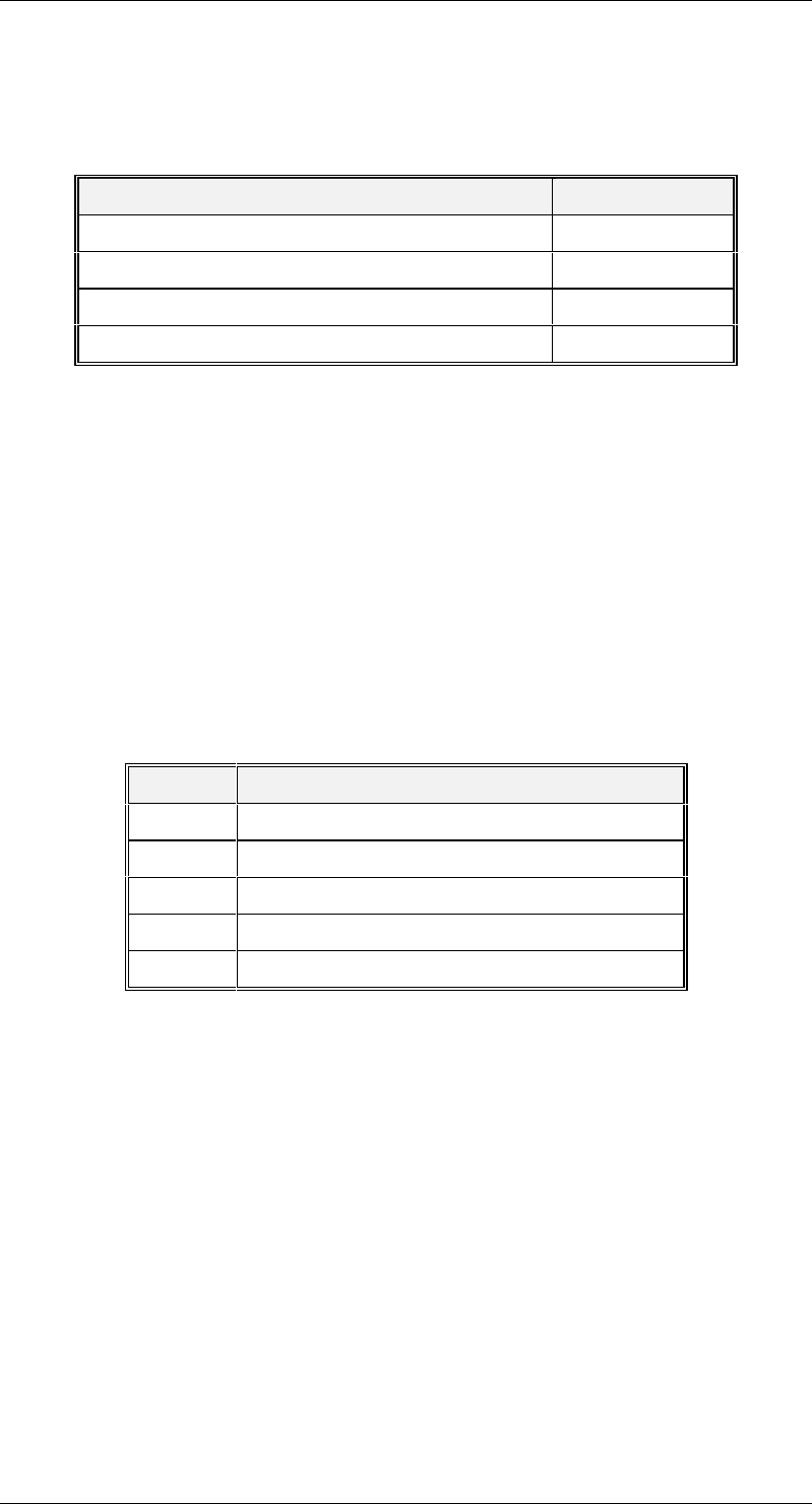
&RQWURO6WDWHV
This section describes the Control characteristics of the Equipment. The Equipment may
be in one of the following control states. This value is reflected in status variable
CONTROLSTATE (VID 1002006).
Value State
1 Off-Line/Equipment Off-Line
2 Off-Line/Attempt On-Line
3 Off-Line/Host Off-Line
4 On-Line/Local
5 On-Line/Remote
GEM for SIPLACE V7.01
©Siemens AG, all rights reserved page 23 of 251
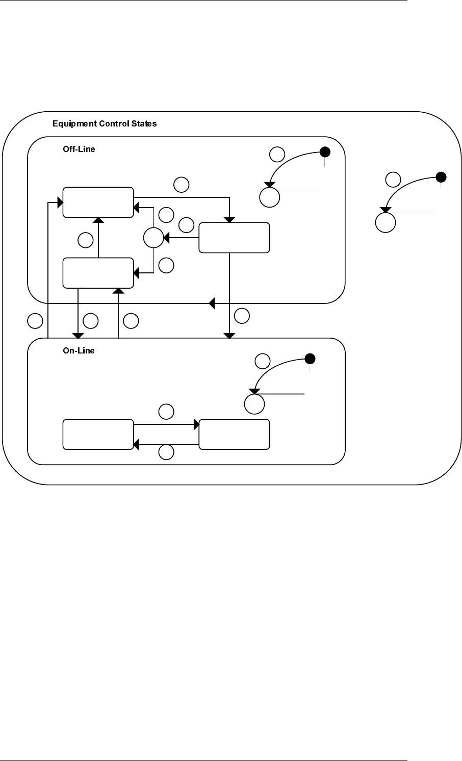
&RQWURO)LQLWH6WDWH'HVFULSWLRQ
The Control State of the Equipment is illustrated in the Control Finite State Diagram. The
SIPLACE behaves differently and will accept different messages depending on its current
control state. The purpose of this diagram is to make clear to the Host exactly what is
happening at the Equipment. The logic for these states and transitions is the logic
specified in the GEM standard.
Equipment C
Off-Line
Host
Off-Line
C
Attempt
On-Line
3
7
5
6
4
C
1
2
Local Remote
12
13
C
11
14 10 9
8