SIPLACE X4 S micron X4i S micron - 第10页
10 Machine performance Placement head types SIPLACE SpeedStar (C&P20 M) SIPLACE MultiStar (CPP) Placement performa nce The placement pe rformance is i nfluenced by the diff erent head combinations a nd hea d position…
9
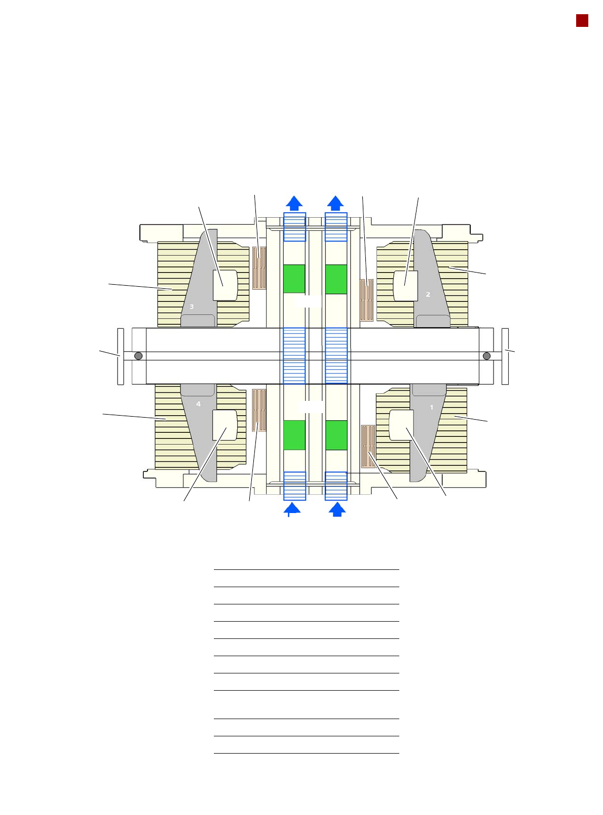
Modular machine concept
Example of SIPLACE X4i S micron
NC
NC
C&P20 M
CPP
NC
NC
PA1
PA2
C&P20 M
COT In
CPP
PA1 Placement area 1
PA2 Placement area 2
OP Operator panel
C&P20 M SIPLACE SpeedStar
CPP SIPLACE MultiStar
NC Nozzle changer
BZ Buffer zone
COT In Changeover table at the inner
position
IN Input area - conveyor
OUT Output area - conveyor
OP
OP
BZ
PLEASE NOTE: For all possible head configurations please refer to section Machine performance from page 10.
COT In
COT In
COT In
IN
OUT
OUT
BZ
IN

10
Machine performance
Placement head types SIPLACE SpeedStar (C&P20 M)
SIPLACE MultiStar (CPP)
Placement performance
The placement performance is influenced by the different head combinations and head positions, plus the
conveyor configurations. Individual options and customized applications also influence the placement perfor-
mance. On request, ASM can calculate the actual performance of your product on your machine configura-
tion.
IPC value [components/h]
According to the vendor-neutral conditions of the IPC 9850 standard published by the Association of Con-
necting Electronics Industries.
SIPLACE benchmark value [components/h]
The SIPLACE benchmark value is measured during the machine acceptance tests. It corresponds to the
conditions set out in the ASM scope of service and supply.
Theoretical maximum output value [components/h]
The theoretical maximum output value is calculated from the most favorable conditions for each machine
type and setting, and corresponds to the theoretical conditions normally used in the industry.
SIPLACE X4 S micron
Placement performance
See the note above for definition of placement performance values.
Placement area 1 Placement area 2 IPC value Benchmark
value
Theoretical
value
C&P20 M / C&P20 M C&P20 M / C&P20 M 82,000
a
a) Without "High Precision" flag
90,000
a
124,000
a
C&P20 M / C&P20 M C&P20 M / C&P20 M 62,000
b
b) With "High Precision" flag
70,000
b
95,000
b
SIPLACE X4i S micron
Placement performance
See the note above for definition of placement performance values.
Placement area 1 Placement area 2 IPC value Benchmark
value
Theoretical
value
C&P20 M / C&P20 M C&P20 M / C&P20 M 102,000 120,000 135,500
C&P20 M / C&P20 M CPP_L/CPP_L 91,500 103,500 123,750
C&P20 M / C&P20 M CPP_H / CPP_H
c
c) CPP_H in placement area 1 only without component camera type 33 (stationary camera)
85,000 100,000 112,500
CPP_H = Multistar CPP in high assembly position
CPP_L = Multistar CPP in low assembly position
11
Placement heads
General
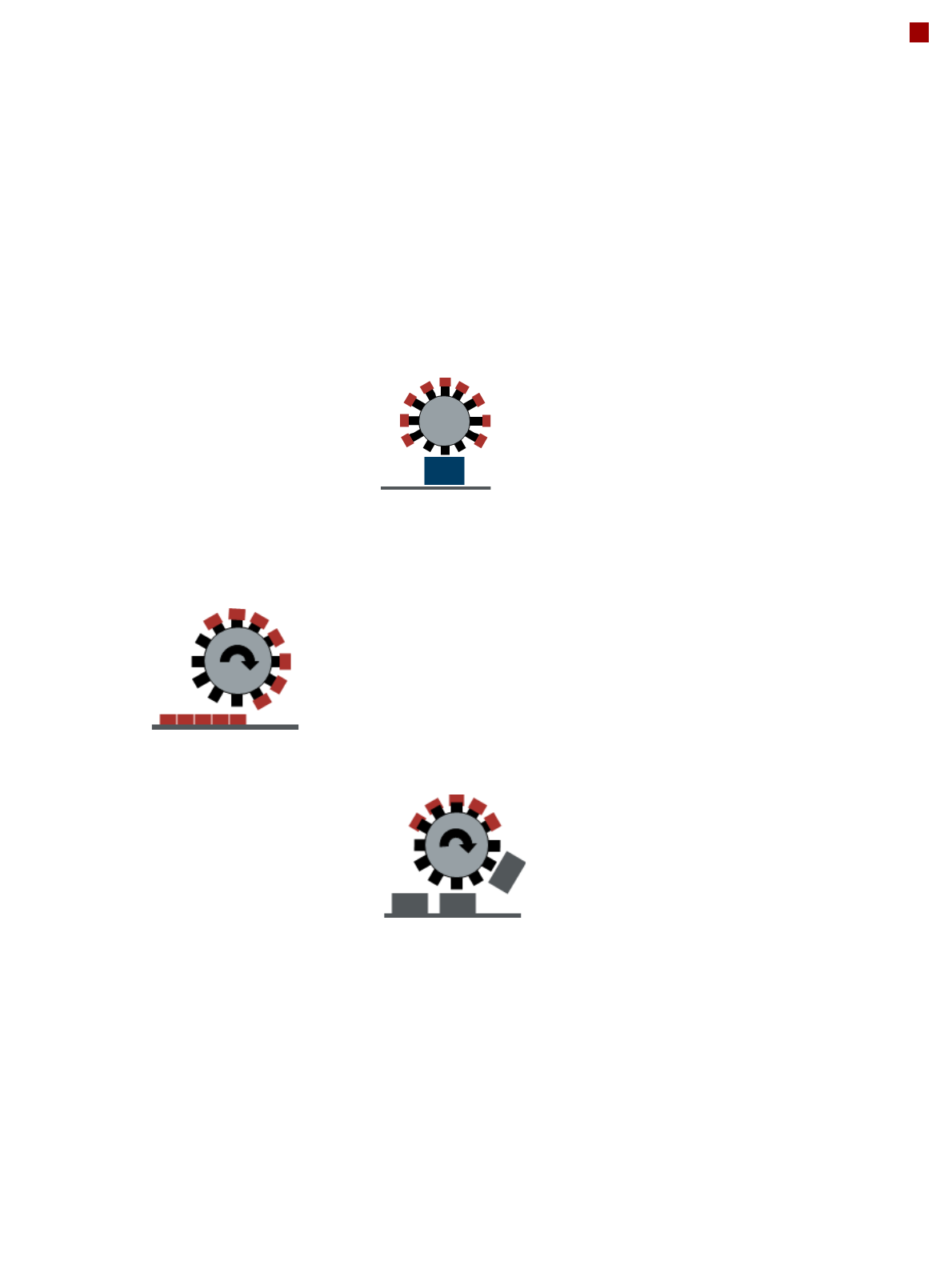
Head modularity
The SIPLACE placement
machines are distinguished
by maximum flexibility in the
production process. This
flexibility is in part due to the
head modularity of the place-
ment machines, which allows
different placement head
variants to be configured to
suit the production require-
ments.
The SIPLACE SpeedStar
and the SIPLACE MultiStar
operate according to the
Collect&Place principle i.e.
one cycle includes pickup or
"collection" of 20 or 12 com-
ponents, their optical center-
ing on the board and their
rotation into the required
placement angle and posi-
tion. They are then placed
gently and accurately onto
the PCB. This principle is
particularly suitable for high-
speed placement of standard
components.
The SIPLACE MultiStar also
functions according to the
Pick&Place principle. Two
components are picked up
by the SIPLACE MultiStar,
optically centered on the way
to the placement position
and rotated into the required
placement angle. This princi-
ple is particularly suitable for
fast and precise placement
of large components.
The SIPLACE MultiStar uses
both the Collect&Place and
the Pick&Place principle.
Mixed Mode allows com-
bined use of these two
modes, which were previ-
ously separated from one
another, in one placement
cycle.
Control and self-learning
functions
The reliability of the
SIPLACE placement heads
can be enhanced even fur-
ther with various checking
and self-learning functions.
• Component sensor
Checks the presence of
the components on the
nozzle before the pickup
and placement process
• Digital camera
Checks the position of
each component on the
nozzle. This check is per-
formed in a single step,
with no extra time involved
but with optimum scan-
ning of each individual
component.
• Force sensor
Monitors the prescribed
component set-down
force.
The sensor stop proce-
dure enables compensa-
tion of height differences
during pickup and PCB
warpage during place-
ment.
• Vacuum sensor
Checks whether the com-
ponent was correctly
picked up or placed.
Collect&Place mode
Pick&Place mode
(SIPLACE MultiStar)
Mixed mode