SIPLACE X4 S micron X4i S micron - 第13页
13 Placement heads SIPLACE MultiStar (CPP) SIPLACE MultiStar (CPP) With component camera type 30 With component camera type 45 With component camer a type 33 (stationary camera) Component range a a) Please note that the …
12
Placement heads
SIPLACE SpeedStar (C&P20 M)
SIPLACE SpeedStar (C&P20 M)
With component camera type
41
Component range
a
a) Please note that the placeable component range is also affected by the pad geometry, the customer-
specific standards, the component packaging tolerances and the component tolerances.
03015 mmto 2220, Melf, SOT,
SOD, Bare-Die, Flip-Chip
Component spec.
Max. height
Min. lead pitch
Min. lead width
Min. ball pitch
Min. ball diameter
Min. dimensions
Max. dimensions
Max. weight
4 mm
0.08 mm
0.03 mm
0.10 mm
0.05 mm
0.12 mm x 0.12 mm
6 mm x 6 mm
1 g
Programmable set-down force 1.5 N - 4.5 N
Nozzle types 10xx, 11xx, 12xx
X/Y accuracy
b
SIPLACE X4 S micron
With "High Precision" flag
Without "High Precision" flag
SIPLACE X4i S micron
b) The benchmark and accuracy values are measured during the machine acceptance tests and corre-
spond to the conditions set out in the ASM scope of service and supply.
± 20 µm / 3σ
± 25 µm / 3σ
± 25 µm / 3σ
Angular accuracy
SIPLACE X4 S micron
SIPLACE X4i S micron
± 0.5° / 3σ
± 0.5° / 3σ
Illumination levels 5
Standard functions High-resolution camera, vacuum sensor, force measurement,
component sensor, integrated turning station per segment, PCB
warpage check, individual image of each component
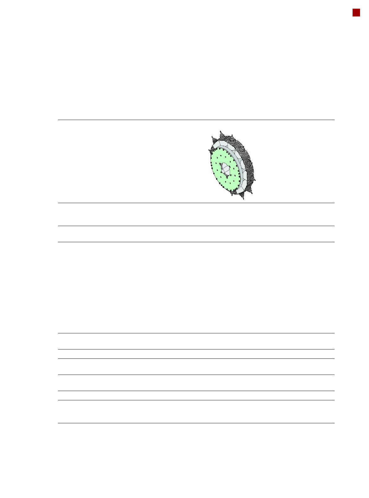
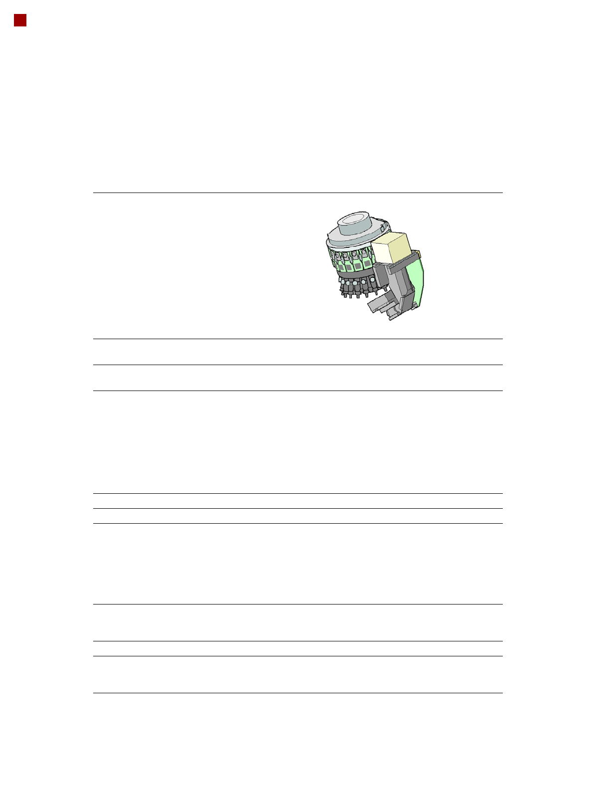
13
Placement heads
SIPLACE MultiStar (CPP)
SIPLACE MultiStar (CPP)
With component camera
type 30
With component camera
type 45
With component camera
type 33
(stationary camera)
Component range
a
a) Please note that the placeable component range is also affected by the pad geometry, the customer-specific stan-
dards, the component packaging tolerances and the component tolerances.
01005 mm to 27 mm x
27 mm
0201 (metric) to
15 mm x 15 mm
0402 to 50 mm x 40 mm
b
b) A diagonal of 69 mm is possible during multiple measurements (e.g. 60 mm x 10 mm).
Component spec.
Max height
c
Max. height
d
Min. lead pitch
Min. lead width
Min. ball pitch
Min. ball diameter
Min. dimensions
Max. dimensions
Max. weight
c) CPP head: in low installation position (stationary component camera not possible).
d) CPP head: in high installation position
6.0 mm
8.5 mm
0.25 mm
0.10 mm
e
/ 0.2 mm
f
0.25 mm
e
/ 0.35 mm
f
0.14 mm
e
/ 0.20 mm
f
0.4 mm x 0.2 mm
27 mm x 27 mm
4 g
e) For components < 18 mm x 18 mm
f) For components ≥ 18 mm x18 mm
6. mm
8.5 mm
0.25 mm / 0.12 mm
g
0.10 mm / 0.05 mm
g
0.25 mm
h
/ 0.14 mm
g
0.14 mm
h
/ 0.07 mm
g
0.18 mm x 0.18 mm
0.11 mm x 0.11 mm
g
15 mm x 15 mm
4 g
g) Only possible for components which are within the camera focal area of ± 1.3 mm.
h) For components < 18 mm x 18 mm
11.5 mm
0.3 mm
0.15 mm
0.35 mm
0.2 mm
1.0 mm x 0.5 mm
50 mm x 40 mm
8 g
Programmable set-down
force
1.0 - 10 N 1.0 - 10 N 1.0 - 10 N
Nozzle types 20xx, 28xx 20xx, 28xx 20xx, 28xx
X/Y accuracy
i
i) The accuracy values are measured during the machine acceptance tests. They correspond to the conditions set
out in the ASM scope of service and supply.
± 41 µm/3σ
± 55 µm/4σ
± 41 µm/3σ
± 55 µm/4σ
± 34 µm/3σ
± 45 µm/4σ
Angular accuracy ± 0.4° / 3σ
j
, ± 0.5° / 3σ
k
± 0.5° / 4σ
j
, ± 0.7° / 4σ
k
j) Component dimensions between 6 mm x 6 mm and 27 mm x 27 mm.
k) Component dimensions smaller than 6 mm x 6 mm.
± 0.4° / 3σ
j
, ± 0.5° / 3σ
k
± 0.5° / 4σ
j
, ± 0.7° / 4σ
k
± 0.2° / 3σ
± 0.3° / 4σ
Illumination levels 5 5 6
Standard functions High-resolution camera, vacuum sensor, force measurement, component sensor,
integrated turning station per segment, PCB warpage check, individual image of
each component
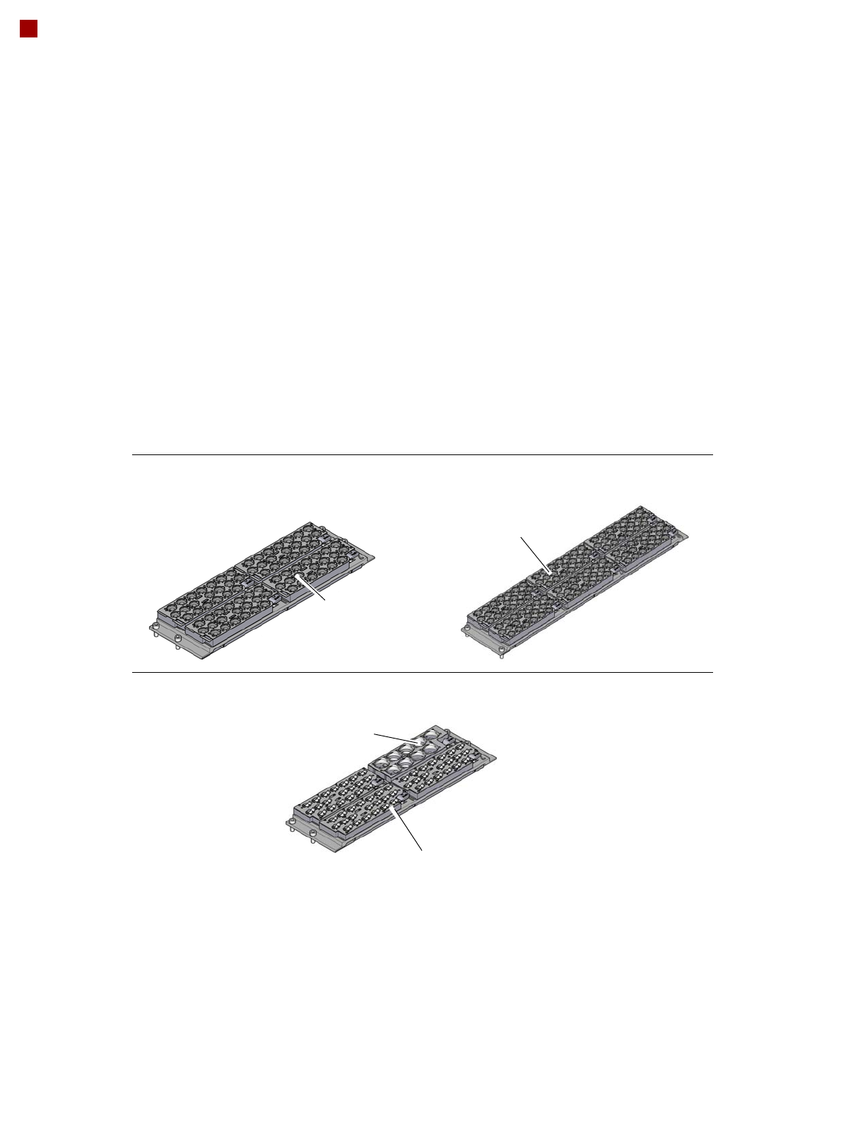
14
Placement heads
Nozzle changer
Nozzle changer for the SIPLACE SpeedStar
Nozzle changer for the SIPLACE MultiStar
4 magazines for 20 nozzles of
type 40xx
6 magazines for 20 nozzles of
type 40xx
Magazine for 9 nozzles of
type 28xx
Magazine for 20 nozzles of type 20xx
Description
Nozzle changers increase the flexibility of the placement heads when it comes to processing
different components. The nozzle configuration can be rapidly adjusted to changing place-
ment jobs. Precisely defined positions and perfect nozzle seat in the garage ensure minimum
radial eccentricity on the placement head.
The nozzle changers feature a monitoring circuit. This checks whether the nozzle magazines
are seated correctly on the mount. In addition, the nozzle changer recognizes whether the
magazines are for 40xx, 20xx or 28xx nozzles by the code.