SIPLACE X4 S micron X4i S micron - 第22页
22 Smart Pin Support General Wide boards tend to deflect during placem ent such that, under certain circumstances, the compon ents can no lon- ger be pl aced with the desired accuracy . Highly curved PCBs also affect the…
21
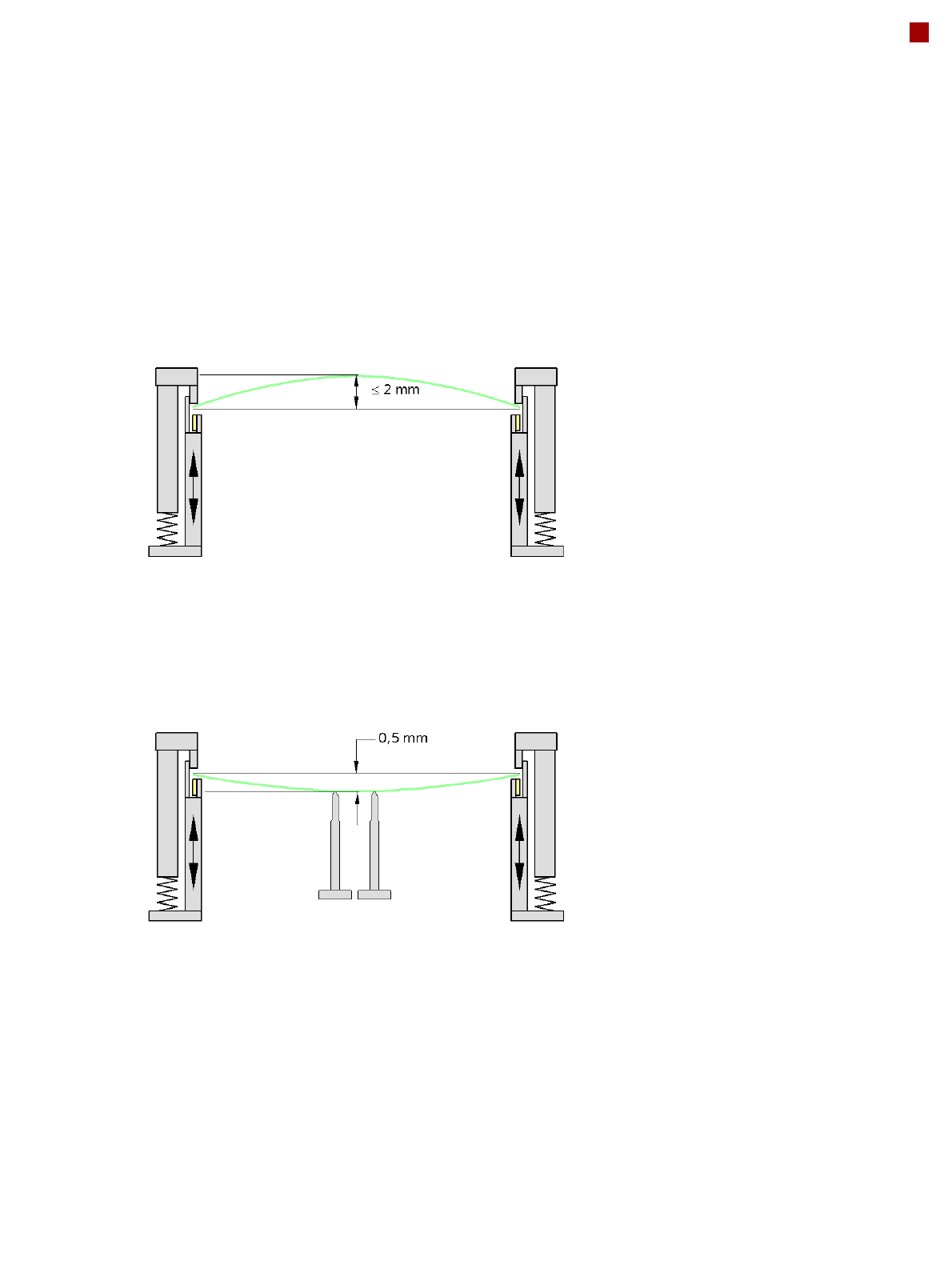
PCB warpage
PCB warpage during placement
PCB warpage downwards max. 0.5 mm
Use the magnetic pin supports, to achieve
this value.
When there is warpage under 2 mm, the
inkspots in the center of the board are also
within the focus of the digital camera. When
all the tolerances are taken into account,
this value is reduced to 1.5 mm.
You should also note that the warpage
reduces the component height.
Magnetic pin support
22
Smart Pin Support
General
Wide boards tend to deflect
during placement such that,
under certain circumstances,
the components can no lon-
ger be placed with the
desired accuracy. Highly
curved PCBs also affect the
placement accuracy. This
problem can be easily recti-
fied by fitting support pins on
the lifting table. The use of
Smart Pin Support enables
you to reduce the number of
feeder locations by a maxi-
mum of 6 locations. It may
also be necessary to use
double setup of components.
This is undertaken automati-
cally by the programming
system.
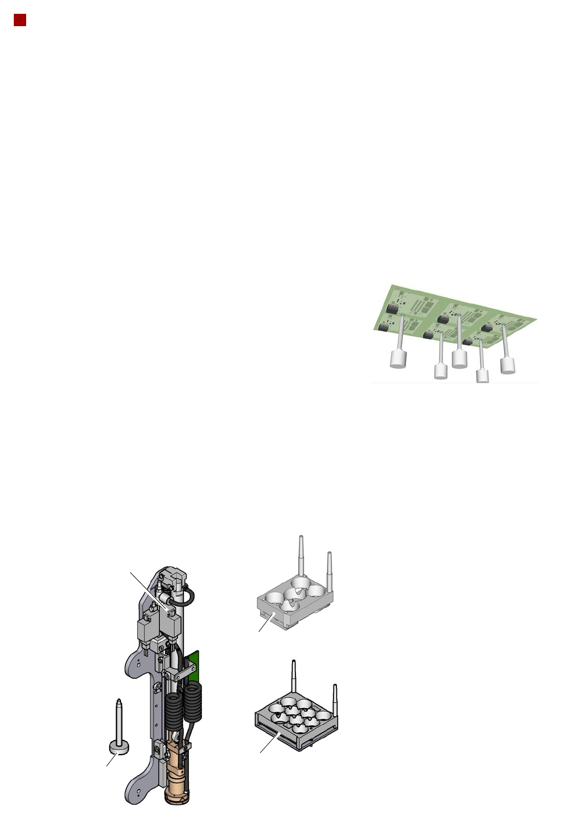
Smart Pin Support
The support pins are auto-
matically placed on the lifting
table with the help of the
Smart Pin Support option.
A gripper unit is used to pick
the support pins up from spe-
cial magazines and place
them in the prescribed posi-
tions.
Before a Smart Support pin
is placed, the position is
cleaned of any contaminants
with a gentle blast of air. In
addition, the correct position-
ing of the support pin is
checked after its placement,
with the PCB camera.
Magazine
There are two different mag-
azines available for auto-
matic changeover of max. 5
or max. 10 support pins in the
various machine configura-
tions. These magazines are
fixed to a magazine holder
and are fitted to the COT
insert.
Programming
The positions of the support
pins in the machine can be
defined for each board side,
in the SIPLACE Pro Board
Editor.
A 3D image of the board and
the support pins allows you
to recognize and prevent any
collision risks between the
support pin and the compo-
nents, even for stepped
transportation of boards with
excess length.
Double setup of components
may be necessary in the
SIPLACE X-Series S,
depending on the board
design and line layout.
SIPLACE Pro takes this into
account automatically.
Gripper unit
Support pin
Magazine W5
Magazine Q 10
23
Component feeding
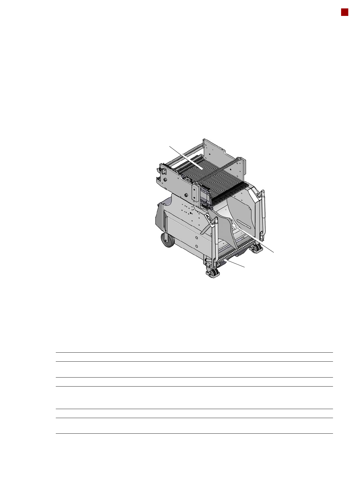
Component trolley X
Component trolley X
The SIPLACE X component
trolleys are independent and
easily maneuverable mod-
ules. Four component trol-
leys, each with 40 tracks, can
be docked onto SIPLACE X
machines. The tape reels are
taken up into the tape con-
tainer of the component trol-
ley. A cutting device on the
machine automatically cuts
up the used tape material.
The component trolleys can
be set up directly on the
machine or at an external
setup area with feeder mod-
ules. The benefits of offline
setup are that the configura-
tions can be prepared with-
out stopping the line.
This allows the setup to be
changed very quickly, using
the changeover table princi-
ple, to rapidly change the
component trolleys.
The SIPLACE X component
trolleys also support fast set-
ting up and tearing down of
feeder modules even during
the placement process.
Tapes can be spliced without
stopping the machine.
For safety reasons, unoccu-
pied locations are fitted with
so-called dummy feeder
modules.
Component trolley X
Tape container
Waste container for remaining empty tape
Changeover table
Component supply Tracks occupied
4 component trolleys X on the SIPLACE X2 S / X3 S / X4 S
4 component trolleys X on the SIPLACE X4i S:
160 feeder modules, each with 8 mm X
148 feeder modules, each with 8 mm X
Tape reel diameter
Standard
Maximum
To 432 mm (17")
483 mm (19")
Component trolley changeover time < 1 minute
Alternative feeder modules with adapter X Tape feeder modules, reject conveyors,
stick magazine and label presenters.