SIPLACE X4 S micron X4i S micron - 第27页
27 Component feeding SIPLACE JTF-S/JTF-M Technical data SIPLACE JTF-S SIPLACE JTF-M Width 162 mm 177 mm Height 587 mm 587 mm JEDEC waffle pack tray spec- ification JEDEC Standard: 95-1 & IEC 60286-5 Storage capa city…
26
Component feeding
SIPLACE JTF-S/JTF-M
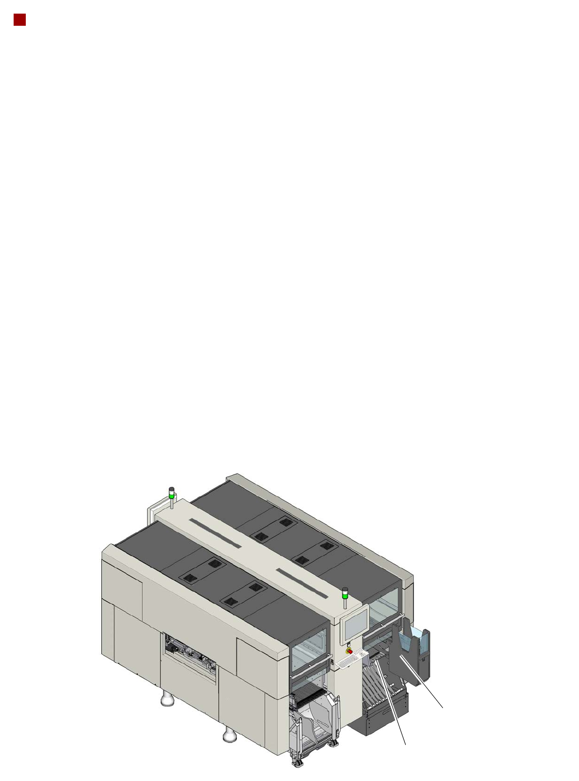
The SIPLACE JTF-S/JTF-M
is an automatic and fast
changer for standard JEDEC
waffle pack trays. When
using the SIPLACE X4i S
micron placement machine,
you can install a SIPLACE
JTF-S/JTF-M on a fixed
table, in place of a
component trolley. The
SIPLACE JTF-S/JTF-M
occupies a fixed area of
tracks on the fixed table.
The SIPLACE JTF-S/JTF-M
is available in two versions
• SIPLACE JTF-S
• SIPLACE JTF-M
SIPLACE JTF-S
The SIPLACE JTF-S stores
a stack of up to 30 thin or 20
thick JEDEC waffle pack
trays and supplies them in
succession. The placement
machine can be supplied
with one component type at
constant waffle pack tray
changeover time.
SIPLACE JTF-M
Depending on the magazine
type, the SIPLACE JTF-M
stores up to 18 thin or 14
thick JEDEC waffle pack
trays in an exchangeable
cassette and supplies them
as required. The placement
machine can therefore be
supplied with different com-
ponent types at variable waf-
fle pack tray changeover
times.
JTF-S/JTF-M
Fixed component table

27
Component feeding
SIPLACE JTF-S/JTF-M
Technical data
SIPLACE JTF-S SIPLACE JTF-M
Width
162 mm 177 mm
Height
587 mm 587 mm
JEDEC waffle pack tray spec-
ification
JEDEC Standard: 95-1 & IEC 60286-5
Storage capacity
Waffle pack tray, thin 30 JEDEC waffle pack trays 18 JEDEC waffle pack trays
Thick waffle pack tray 20 JEDEC waffle pack trays 14 JEDEC waffle pack trays
Waffle pack tray changeover
time
< 5 seconds (depending on
application)
--
Slot n to n+1 -- 3.5 seconds
Slot 1 to 18 -- 10 seconds
Slot 18 to 1 -- 8.9 seconds
Cassette
--
Dimensions -- approx. 330 mm x 150 mm x 230
mm
Max. load capacity -- 2.7 kg (150 g each for 18 slots)
Pneumatics
4.1 bar to 5.5 bar 5.2 bar to 9 bar
Compressed air consumption
< 28.3 NL/min. < 28.3 NL/min.

28
SIPLACE Vision
High placement performance and best quality
SIPLACE Vision is designed
to recognize and measure
components and boards
(substrates), so that these
can then be placed and con-
nected precisely.
In the placement area,
SIPLACE Vision determines
the position of the compo-
nent on the nozzle and there-
fore facilitates exact
positioning of components
on the printed circuit boards.
There is a large component
library available which
already contains all standard
component shapes. Wizard
assistants, such as the Com-
ponent Shape Wizard, make
it easier to create new com-
ponent shapes.
Component recognition
SIPLACE Vision identifies each individual component by its geometry and color. Even complex com-
ponent shapes are detected with high reliability. This component recognition check is performed in a
single step, with no extra time involved but with optimum scanning of each individual component. The
camera types are adjusted to the various head types and present a range of different resolutions, field
of vision sizes, illumination types and focal areas. See also the technical data for the relevant place-
ment heads from page 11 onwards. With the help of different illumination levels and brightness
stages, almost every component shape can be easily recognized. The system also saves images of
the components, so-called "Vision dumps". These enable you to analyze rejected components and to
further improve component shape descriptions. This supports the early recognition of faults in new
products and increases process reliability. These vision dumps also serve as evidence in the event of
defective component supplies.
Component recognition is used for:
• Tolerance checks for component dimensions, L x W, (shape)
• Tolerance checks for component features e.g.:
• Lead/ball grids
• Lead/ball length/diameter
• Deformed leads/missing balls
• Damage/discoloration
• Flipped/face down
• Vision dumps in the event of malfunctions
• Pin 1 / polarity recognition
• Pattern matching
• Glue dot inspection
• Reading component barcodes/data matrix codes
• Pickup reliability
• Pocket measurement
• Tray measurement
• Offset of component to nozzle center and dynamic correction of pickup position