00193733-02.pdf - 第52页
2 Assembly Instructions PCB Camera, Multicolor SIPLACE F5 HM SIPLACE F5 HM 2.5 Preparatory Steps 05/2007 Edition 52 2.5 Prep aratory S tep s : Open the safety hoods and the safety d oors on the area of component fe eders…

SIPLACE F5 HM 2 Assembly Instructions PCB Camera, Multicolor SIPLACE F5 HM
05/2007 Edition 2.3 Requirements
51
2.3 Requirements
– Software version 407.01 or later.
2.4 Assembly Kits, Tools
2.4.1 Assembly Kit "PCB Camera Multicolor F5 HM"
1 Unit Assembly kit "Multicolor for F5 HM", item no.: 00358028-01, consisting of: 2
- PCB camera Multicolor Item no. 00355462-01 1 unit
- Assembly kit V50 currency Item no. 00357863-01 1 unit
2.4.2 Additional Material Required
- Cable tie L x W = 140 x 3.6 mm Item no.: 00805141-01 x units
- Cable clamp, size 6. Item no.: 00805503 8 units
- Aderendhülsen xxxxxxxx 5 units
NOTE:
No additional screws are needed to mount the PCB camera Multicolor. The captive screws are on
the PCB camera Multicolor. 2
2.4.3 Tools, Auxiliary Test Equipment and Expendable Materials
– Set of Allen wrenches
– Oblique-nosed cutting pliers
– Wire stripper
– ESD bracelet
– Small mirror to be used as an aid while installing/removing the PCB camera
2 Assembly Instructions PCB Camera, Multicolor SIPLACE F5 HM SIPLACE F5 HM
2.5 Preparatory Steps 05/2007 Edition
52
2.5 Preparatory Steps
: Open the safety hoods and the safety doors on the area of component feeders.
: Push the gantry out of the vicinity of the component changeover table until it is above the PCB
conveyor area.
: Turn the machine off at the main switch, isolate the machine from the mains, turn OFF the flow
of compressed air at the compressed air unit (see DANGER text in Abschn. 2.2).
: Push the X-gantry toward the outside of the machine so that the placement head is readily ac-
cessible.
SIPLACE F5 HM 2 Assembly Instructions PCB Camera, Multicolor SIPLACE F5 HM
05/2007 Edition 2.6 Assembly Terminal panels and Illumination cable
53
2.6 Assembly Terminal panels and Illumination cable
2.6.1 Assembling in the Terminal Panel, Right Side
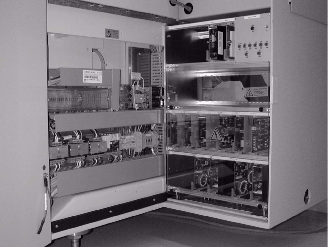
Abb. 2.6.1 Opening the Machine Frame Doors (Service Cabinets for Terminal Panel, Right Side)
Key:
1. Machine frame doors
2. Lateral protection (remains installed)
: Open the machine frame doors on the terminal panel, right side: see Abb. 2.6.1.
: Loosen the screw fastening the servo unit (loosen the M5 socket hex head screw) and lift the
servo unit out.
: Use the following Abb. 2.6.2 and the circuit diagram, Fig. 2.13.6: