00193733-02.pdf - 第54页
2 Assembly Instructions PCB Camera, Multicolor SIPLACE F5 HM SIPLACE F5 HM 2.6 Assembly Terminal panels and Illumination cable 05/2007 Edition 54 2.6.1.1 Install ation Step s in the T ermi nal Panel, Right Side Abb. 2.6.…
SIPLACE F5 HM 2 Assembly Instructions PCB Camera, Multicolor SIPLACE F5 HM
05/2007 Edition 2.6 Assembly Terminal panels and Illumination cable
53
2.6 Assembly Terminal panels and Illumination cable
2.6.1 Assembling in the Terminal Panel, Right Side
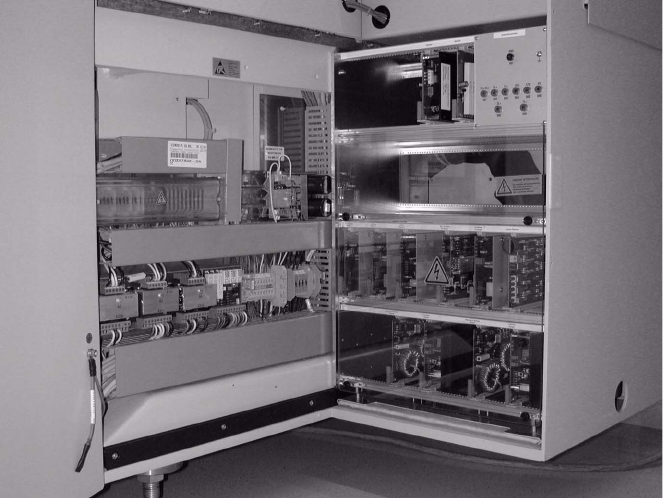
Abb. 2.6.1 Opening the Machine Frame Doors (Service Cabinets for Terminal Panel, Right Side)
Key:
1. Machine frame doors
2. Lateral protection (remains installed)
: Open the machine frame doors on the terminal panel, right side: see Abb. 2.6.1.
: Loosen the screw fastening the servo unit (loosen the M5 socket hex head screw) and lift the
servo unit out.
: Use the following Abb. 2.6.2 and the circuit diagram, Fig. 2.13.6:
2 Assembly Instructions PCB Camera, Multicolor SIPLACE F5 HM SIPLACE F5 HM
2.6 Assembly Terminal panels and Illumination cable 05/2007 Edition
54
2.6.1.1 Installation Steps in the Terminal Panel, Right Side
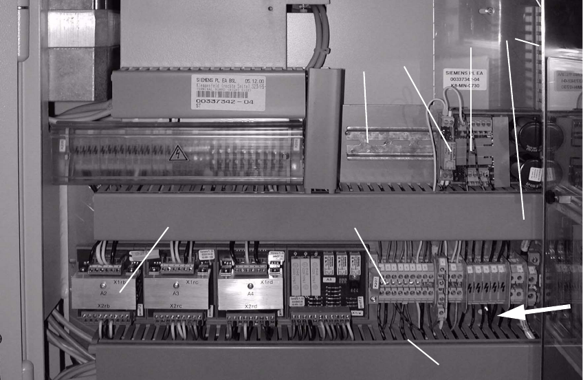
Abb. 2.6.2 Terminal Panel, RH Side: X207; Location for Install. Voltage Module 50 V + Relay K1
Key: 2
1. Servo-unit (remove)
2. Cable pits: remove cover
3. Top hat rail
4. 50 V voltage regulator module 50 F5 HM
5. Relay K1 F5 HM
6. Terminal strip X207
7. Rectifier module A2
2
: Clip the 50 V voltage regulator module (= converter, Item no. 00349095-01, see assembly kit)
onto the top hat rail on the RH side.
: Clip the relay K1 left, onto the top hat rail next to the voltage regulator module.
1
2
4
5
3
6
7
2

SIPLACE F5 HM 2 Assembly Instructions PCB Camera, Multicolor SIPLACE F5 HM
05/2007 Edition 2.6 Assembly Terminal panels and Illumination cable
55
2.6.1.2 Conducting the Wiring in the Terminal Panel, Right Side
: Remove the cover from the horizontal and vertical cable pit.
: Remove the green strand running from rectifier module A2: X7 to terminal X207-1
(layout A2: see Abb. 2.6.2). The terminal X207-1 is then not in use.
: Run the cables W1 to W5 from the assembly kit as shown in the overview, Fig. 2.13.7.
Prefabricate the cables as much as possible.
NOTE:
You will need a size 1 screwdriver to disconnect and make the Catch terminal connections and
terminal connections X 207. 2
: Lay and wire the new cables W1 to W5 as shown in circuit diagram Fig. 2.13.8 AND, while
doing so, assemble cables W2 and W3 as follows:
– Install a twin connector sleeve at cable end W2 that will be connected to X207-3 and at ca-
ble end W3 that will be connected to X207-5.
– Use the crimp pliers to fasten each of the two strands bl/bk in the twin connector sleeve.
– Clamp the cables W2 thus assembled to X 207-3 and W3 to X 207-5.
: Make certain that all connections are firmly seated and are correctly allocated.
2