00193733-02.pdf - 第55页
SIPLACE F5 HM 2 Assembly Instructions PCB Camera, Multicolor SIPLACE F5 HM 05/2007 Edition 2.6 Assembly Term inal pan els and Illumination cable 55 2.6.1.2 Conducting the Wiring in the T erminal Panel, Right Side : Remov…
2 Assembly Instructions PCB Camera, Multicolor SIPLACE F5 HM SIPLACE F5 HM
2.6 Assembly Terminal panels and Illumination cable 05/2007 Edition
54
2.6.1.1 Installation Steps in the Terminal Panel, Right Side
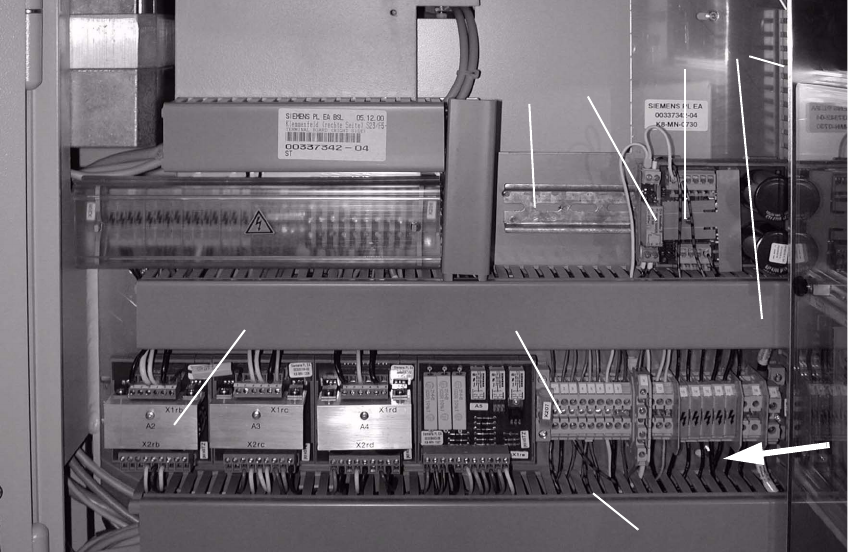
Abb. 2.6.2 Terminal Panel, RH Side: X207; Location for Install. Voltage Module 50 V + Relay K1
Key: 2
1. Servo-unit (remove)
2. Cable pits: remove cover
3. Top hat rail
4. 50 V voltage regulator module 50 F5 HM
5. Relay K1 F5 HM
6. Terminal strip X207
7. Rectifier module A2
2
: Clip the 50 V voltage regulator module (= converter, Item no. 00349095-01, see assembly kit)
onto the top hat rail on the RH side.
: Clip the relay K1 left, onto the top hat rail next to the voltage regulator module.
1
2
4
5
3
6
7
2

SIPLACE F5 HM 2 Assembly Instructions PCB Camera, Multicolor SIPLACE F5 HM
05/2007 Edition 2.6 Assembly Terminal panels and Illumination cable
55
2.6.1.2 Conducting the Wiring in the Terminal Panel, Right Side
: Remove the cover from the horizontal and vertical cable pit.
: Remove the green strand running from rectifier module A2: X7 to terminal X207-1
(layout A2: see Abb. 2.6.2). The terminal X207-1 is then not in use.
: Run the cables W1 to W5 from the assembly kit as shown in the overview, Fig. 2.13.7.
Prefabricate the cables as much as possible.
NOTE:
You will need a size 1 screwdriver to disconnect and make the Catch terminal connections and
terminal connections X 207. 2
: Lay and wire the new cables W1 to W5 as shown in circuit diagram Fig. 2.13.8 AND, while
doing so, assemble cables W2 and W3 as follows:
– Install a twin connector sleeve at cable end W2 that will be connected to X207-3 and at ca-
ble end W3 that will be connected to X207-5.
– Use the crimp pliers to fasten each of the two strands bl/bk in the twin connector sleeve.
– Clamp the cables W2 thus assembled to X 207-3 and W3 to X 207-5.
: Make certain that all connections are firmly seated and are correctly allocated.
2
2 Assembly Instructions PCB Camera, Multicolor SIPLACE F5 HM SIPLACE F5 HM
2.6 Assembly Terminal panels and Illumination cable 05/2007 Edition
56
2.6.2 Assembling in the Terminal Panel, LH Side
2.6.2.1 Changing the "Illumination" Cables
The F5 HM has 2 "illumination" cables: 2
– Cable "illumination, gantry 1": Item no. 00244260-xx
– Cable "illumination, gantry 2": Item no. 00244261-xx
These cables must be changed first, as described below.
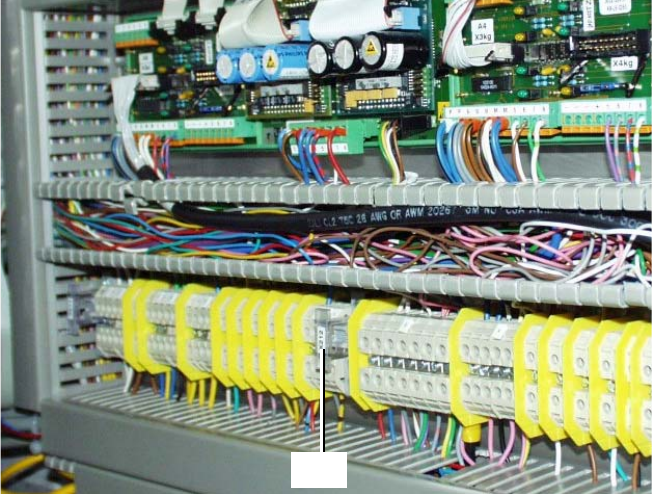
Abb. 2.6.3 Terminal Panel, LH Side, Layout of the Illumination Cables, Gantries 1 and 2
: Open the machine frame doors for terminal panel, LH side.
: Use the circuit diagram Fig. 2.13.6 and change the two cables "illumination, gantry 1" and "2"
as follows:
– Separate the strands wh, gn, gr, bl which are clamped to terminal X212 - 4 with a connector
sleeve.
– Use the crimping pliers. Now clamp these strands separately as follows, each in a twin con-
nector sleeve from the assembly kit (Section 2.4.3):
- wh with gn
- gr with bl
: Clamp the 2 changed "Illumination" cables on the terminal panel:
– the strands wh, gn -> to terminal X212 - 4 (+ 24V),
– the strands gn, bl -> to terminal X212 - 9 (+ 50V)
3
4
X212