00193733-02.pdf - 第59页
SIPLACE F5 HM 2 Assembly Instructions PCB Camera, Multicolor SIPLACE F5 HM 05/2007 Edition 2.6 Assembly Term inal pan els and Illumination cable 59 : Set the PCB camera down carefully so tha t it won’t be damaged. The be…
2 Assembly Instructions PCB Camera, Multicolor SIPLACE F5 HM SIPLACE F5 HM
2.6 Assembly Terminal panels and Illumination cable 05/2007 Edition
58
: If the optional oblique illumination (see Abb. 2.6.5) is present on the subgantry PCB camera,
deinstall the oblique illumination as follows:
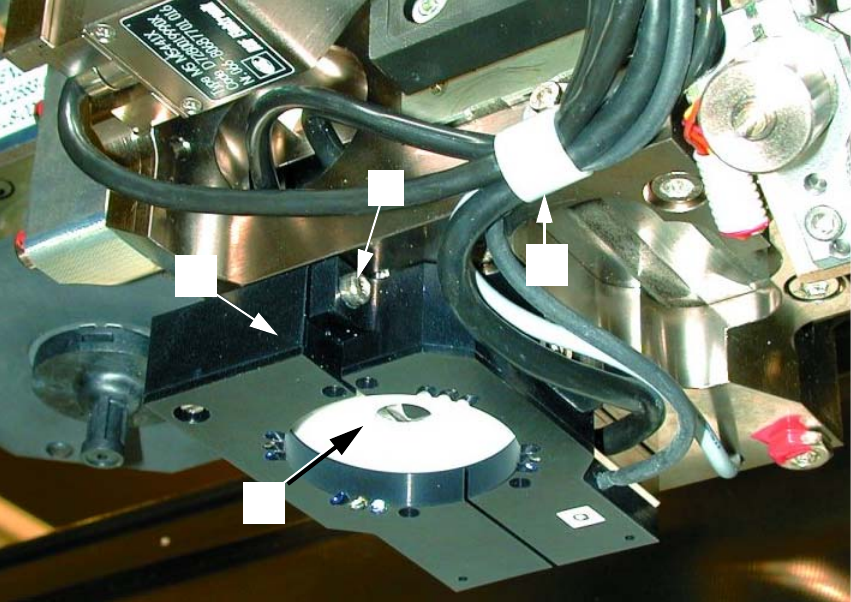
Abb. 2.6.5 Removing the Optional Oblique Illumination
Key: 2
1. Subgantry PCB camera
2. Cable clip: Fastener = 1 socket hex head cap screw M3
3. Optional oblique illumination
4. Fastener for oblique illumination: an attachment screw (socket hex head cap screw M 3)
2
: Undo the cable clip fastener (see Abb. 2.6.5 -> 2).
: Hold onto the oblique illumination:
Undo the attachment screw (socket hex head cap screw M3: see Abb. 2.6.5 -> 2) and pull the
oblique illumination straight down and off the camera.
: Cautiously put the oblique illumination to one side so that it won’t be damaged. The best pro-
cedure is to put it into a suitable package immediately.
: Use a small mirror as an aid and HOLD onto the PCB camera:
Starting from the bottom, undo the screws fastening the PCB camera (3 socket hex head cap
screws M2, see Abb. 2.6.4 -> 4) and lower the PCB camera out.
3
1
2
4
SIPLACE F5 HM 2 Assembly Instructions PCB Camera, Multicolor SIPLACE F5 HM
05/2007 Edition 2.6 Assembly Terminal panels and Illumination cable
59
: Set the PCB camera down carefully so that it won’t be damaged. The best procedure is to place
it in a suitable package immediately.
2.6.4 Installing the PCB Camera Multicolor
NOTE:
Find out before installing the PCB camera Multicolor which PCB or substrate thickness will be
place next. Depending on the thickness, it will or will not be necessary to place the distance plate
(spacer) from the assembly kit under each camera.
The table below is helpful during assembly process. In deciding, calculations are carried out to
ascertain which thickness range the current PCB or substrate thickness is closest to the FOCUS.
Following the configuration of the Multicolor PCB camera at the line computer, including descri-
bing the PCB or substrate (entry of the thickness), a message can be accessed at the line com-
puter as a check (see Abschn. 2.7.2).
If the distance plates are not required at the present time, make certain that they are stored such
that they will be available to the line engineer/service engineer for later installation. 2
The following data items are recommendations to ensure an optimal placement process: 2
In most cases, adequate imaging quality will still be achieved even it work is done outside the ran-
ges indicated above.
With the spacer plate removed, system fiducials can still be adequately recognized. 2
PCB or substrate thickness Focus Install distance plate (spa-
cer)
0.3 - 3.4 mm 1.7 mm Yes
1.5 - 4.5 mm 3.2 mm No
2 Assembly Instructions PCB Camera, Multicolor SIPLACE F5 HM SIPLACE F5 HM
2.6 Assembly Terminal panels and Illumination cable 05/2007 Edition
60
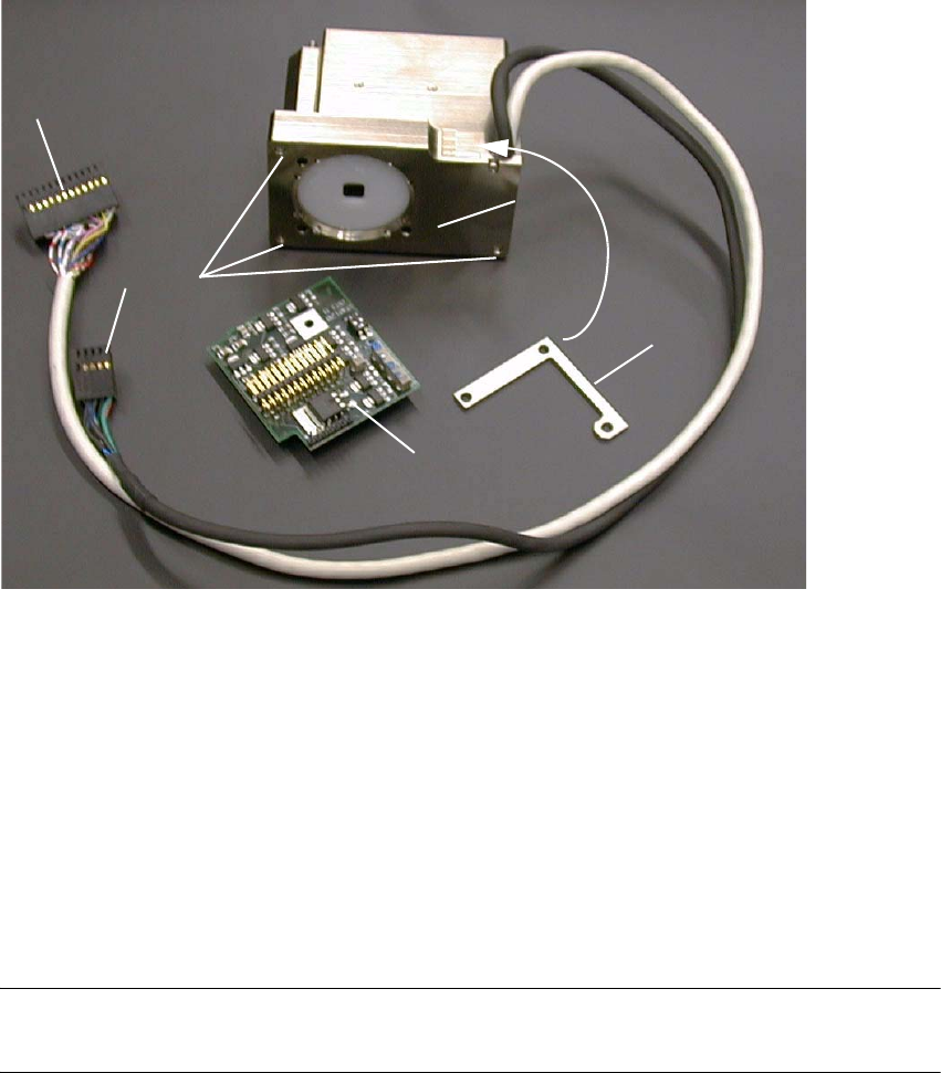
Abb. 2.6.6 PCB Camera Multicolor Assembly with Distance Plate (Spacer)
Key: 2
1. Distance plate (Spacer) *)
2. PCB camera Multicolor incl. cable and connector *)
3. Fasteners for PCB camera Multicolor: 3 hex head cap screws M3 x 14, captive *)
4. "PCB camera board, modular" *)
5. Cable "illumination", camera *) -> Connection to X3 at "PCB (camera) board modular"
6. Cable "camera" *) -> Connection to X4 at "Vision board, modular"
*) Components of the assembly kit PCB camera Multicolor
NOTE.
PCB camera Multicolor and "PCB camera board, modular," constitute a mutually attuned unit. 2
: When removing the components from the package for the first time, check to make certain that
the serial number on the camera is identical with the number on the "PCB camera board, mo-
dular" (see Abb. 2.6.8).
: Beginning from the bottom of the gantry, screw the 3 new spacer bolts (L = 8.5 mm) from the
assembly kit into the camera holder (6 mm open-end / socket wrench).
: Ascertain the PCB/substrate thickness to be processed now.
2
1
3
4
5
6