00193733-02.pdf - 第64页
2 Assembly Instructions PCB Camera, Multicolor SIPLACE F5 HM SIPLACE F5 HM 2.6 Assembly Terminal panels and Illumination cable 05/2007 Edition 64 : Lay the cables "Illumination" and "Camera" in the ar…
SIPLACE F5 HM 2 Assembly Instructions PCB Camera, Multicolor SIPLACE F5 HM
05/2007 Edition 2.6 Assembly Terminal panels and Illumination cable
63
2.6.6 Laying Cables, Plugging into PCB Camera Board and Vision Board
: Run the two cables from the PCB camera Multicolor up to the head PCBs (see Fig.).
: Plug the connectors of the PCB camera Multicolor into the "Vision board modular" and into the
"PCB camera, modular" located above it (Abb. 2.6.9).
Layout of the PCBs -> see Fig. 2.13.1 and Fig. 2.13.2.
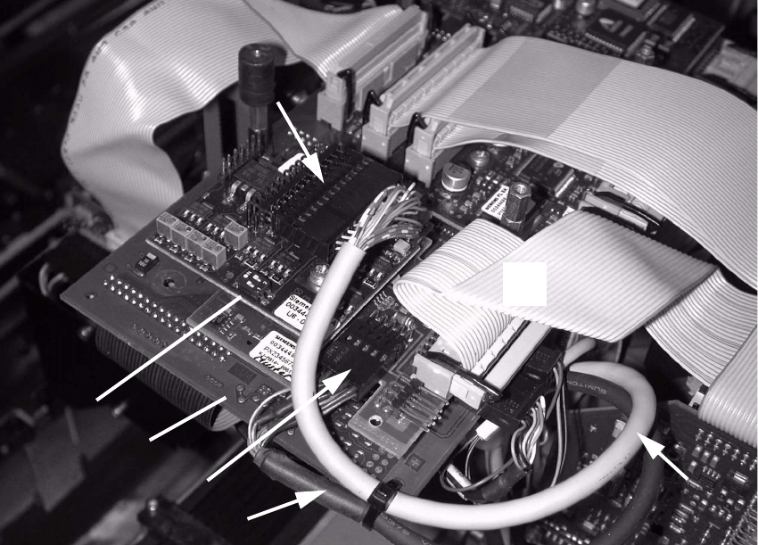
Abb. 2.6.9 Plug In the Connectors of the PCB Camera Multicolor
Key: 2
1. Vision board, modular
2. Plug-type connector on X4: Cable "Camera" of PCB Camera Multicolor
3. PCB camera board, modular
4. Plug-type connector on X3: Cable "illumination" of PCB camera Multicolor
5. Correct cable layout: = above the PCB: See Abb. 2.6.10, NOTE
6. Cable "illumination" of PCB Camera Multicolor
2
2
2
2
4
3
1
5
2

2 Assembly Instructions PCB Camera, Multicolor SIPLACE F5 HM SIPLACE F5 HM
2.6 Assembly Terminal panels and Illumination cable 05/2007 Edition
64
: Lay the cables "Illumination" and "Camera" in the area of the modular head PCB unit (Abb.
2.6.10).
: Fasten the cables running upward such that the strain on the connectors is relieved (Fig.
2.6.10).
For this you will need size 6 cable clamps and the screws M3 and M4 available as a result of
the previous disassembly.
2
: Lay the cables "Camera" and "Illumination" in the area of the head PCB (Abb. 2.6.10 -> 3 and
1).
: Using cable ties, fasten the cable "Camera" in the hole in the vision board, modular (-> 5).
: Fasten the cable "Illumination" to the spacer bolt with the cable tie (-> 9).
: Fold the preshaped ribbon cable down so that it lies flat (Abb. 2.6.10 -> 7).
Key to Abb. 2.6.10: 2
1. Cable "Illumination" of PCB camera Multicolor
2. Cable "Illumination" -> plug-in connection X3 (PCB camera board, modular)
3. Cable "Camera" of PCB camera Multicolor
4. Cable "Camera" -> plug-in connection X4 (Vision board, modular)
5. Cable tie: fastening of cable "Camera" of PCB camera Multicolor *)
6. Ribbon cable lying at bottom, new, contained at Item no. 00358917-01
(available due to assembly of the modular head PCB F5 HM)
7. Preshaped ribbon cable, new, contained at Item no. 00351063-01
(available due to assembly of the modular head PCB F5 HM)
8. Ribbon cable lying at top, contained at Item no. 00358917-01
(available due to assembly of the modular head PCB F5 HM)
9. Cable tie: fastening the cable "Illumination" of PCB camera Multicolor
10.Flexible lead br/bl: exists ONLY on the test machine shown in this photograph.
11.3 ribbon cables, 10-pin (units for positioning, e.g. turning station) and 1 ribbon cable, 16-pin
(vacuum):
Attention: If the strain relief device cannot be mounted on F5 HM, new connectors must be
mounted as described in the assembly instructions for "Modular head PCBs for F5 HM".
NOTE:
Final solution = Hole in the vision board to fasten a cable tie. The cable be laid ON the PCB and,
in order for the head cover to fit, the cable is not to protrude over the sides. The cable is fastened
to the vision board with cable ties. 2
SIPLACE F5 HM 2 Assembly Instructions PCB Camera, Multicolor SIPLACE F5 HM
05/2007 Edition 2.6 Assembly Terminal panels and Illumination cable
65
2
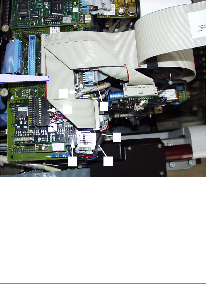
Abb. 2.6.10 1st Step while Laying Cable in the Area of the Head PCB
Key to Abb. 2.6.10: 2
1. Cable "Illumination" of PCB camera Multicolor
2. Cable "Illumination" -> plug-in connection X3 (PCB camera board, modular)
3. Cable "Camera" of PCB camera Multicolor
4. Cable "Camera" -> plug-in connection X4 (Vision board, modular)
5. Cable tie: fastening of cable "Camera" of PCB camera Multicolor *)
6. Cable tie: fastening the cable "Illumination" of PCB camera Multicolor
NOTE:
The cable be laid ON the PCB and, in order for the head cover to fit, the cable is not to protrude
over the sides. The cable is fastened to the vision board with cable ties. 2
2
1
1
4
3
5
2
6