00193733-02.pdf - 第79页
SIPLACE F5 HM 2 Assembly Instructions PCB Camera, Multicolor SIPLACE F5 HM 05/2007 Edition 2.12 Illumination Setting 79 : Select the button "Positioning the gantry" an d po sition the gan try over the fiducial …
2 Assembly Instructions PCB Camera, Multicolor SIPLACE F5 HM SIPLACE F5 HM
2.12 Illumination Setting 05/2007 Edition
78
2.12.3 Setting the Illumination
The best illumination selection must be ascertained by using the function "Test fiducials" or the
substrate to be populated. 2
NOTE:
The processes which must be executed prior to setting the illumination are described in detail in
the section "Teaching Fiducials" or "Teaching Synthetic Fiducials" of the User Manual, Software
version SR 407.xx.
During them, the current substrate or PCB is moved onto the processing belt of the conveyor and
mechanically centered / clamped in place. 2
: Select the ICON "Setting illumination"
: In the "illumination" menu select the "Setting illumination" button.
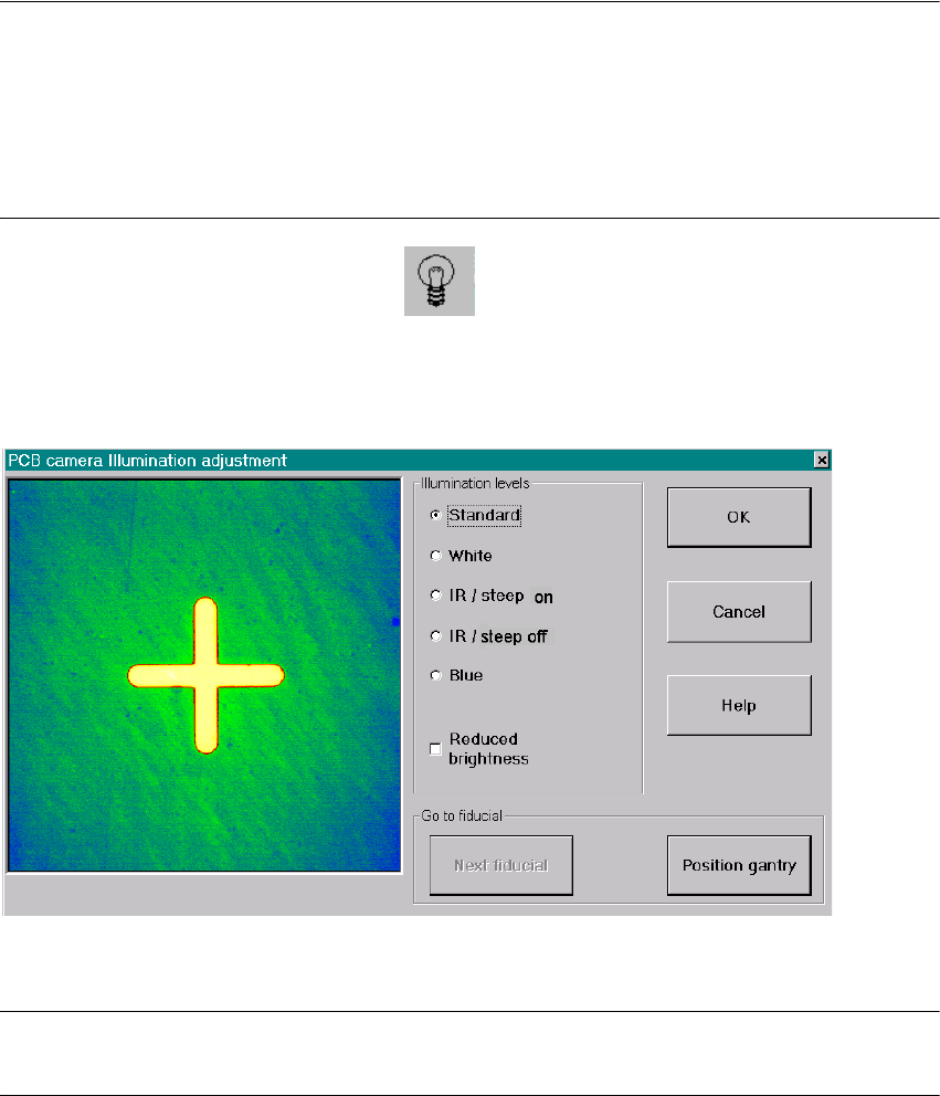
The following screen will appear:
Fig. 2.12.1 Screen: "Setting the Illumination"
NOTE:
Utilize Abschn. 2.12.2 and the table in Abschn. 2.12.3 to select the best type of illumination. 2
: Select the desired illumination level by activating the pertinent radio button.
: Select the complete or the reduced brightness by activating or deactivating the rectangular
field.
SIPLACE F5 HM 2 Assembly Instructions PCB Camera, Multicolor SIPLACE F5 HM
05/2007 Edition 2.12 Illumination Setting
79
: Select the button "Positioning the gantry" and position the gantry over the fiducial that is cur-
rently to be recognized / tested.
: Check the quality of the image on the vision screen (see the section "Teaching Fiducials" in the
User Manual).
: If the image of the fiducial is still not optimal, select another illumination level or, if appropriate,
change the brightness too and select the button "Positioning the gantry" again.
: If the image of the fiducial is alright, select the button "OK".
2
2
2
2
2
2
2
2
2
2
2
2
2
2
2
2
2
2
2
2
2
2
2 Assembly Instructions PCB Camera, Multicolor SIPLACE F5 HM SIPLACE F5 HM
2.13 Attachments: PCBs, Cables and Circuit Diagrams 05/2007 Edition
80
2.13 Attachments: PCBs, Cables and Circuit Diagrams
2.13.1 Layout: PCB Camera Board and Vision Board, Modular
2
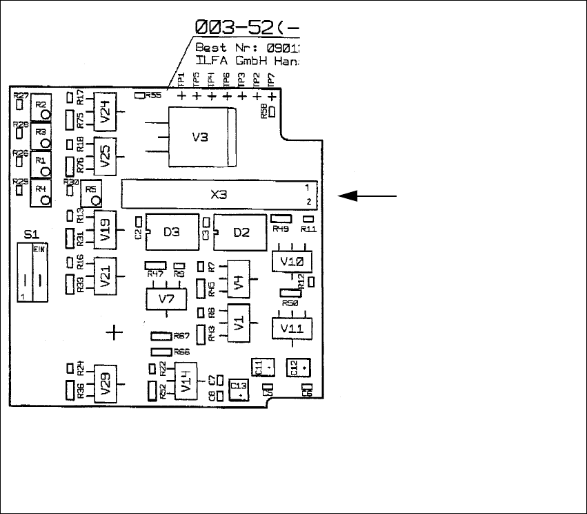
Fig. 2.13.1 Layout: PCB Camera Board, Modular
Layout, component side
Cable
Illumination of the
PCB camera
Multicolor --> X3