00193733-02.pdf - 第80页
2 Assembly Instructions PCB Camera, Multicolor SIPLACE F5 HM SIPLACE F5 HM 2.13 Attachments: PCBs, Cables and Circuit Diagrams 05/2007 Edition 80 2.13 Att achment s: PCBs, Ca bles and Circuit Diagrams 2.13.1 Layout: PCB …
SIPLACE F5 HM 2 Assembly Instructions PCB Camera, Multicolor SIPLACE F5 HM
05/2007 Edition 2.12 Illumination Setting
79
: Select the button "Positioning the gantry" and position the gantry over the fiducial that is cur-
rently to be recognized / tested.
: Check the quality of the image on the vision screen (see the section "Teaching Fiducials" in the
User Manual).
: If the image of the fiducial is still not optimal, select another illumination level or, if appropriate,
change the brightness too and select the button "Positioning the gantry" again.
: If the image of the fiducial is alright, select the button "OK".
2
2
2
2
2
2
2
2
2
2
2
2
2
2
2
2
2
2
2
2
2
2
2 Assembly Instructions PCB Camera, Multicolor SIPLACE F5 HM SIPLACE F5 HM
2.13 Attachments: PCBs, Cables and Circuit Diagrams 05/2007 Edition
80
2.13 Attachments: PCBs, Cables and Circuit Diagrams
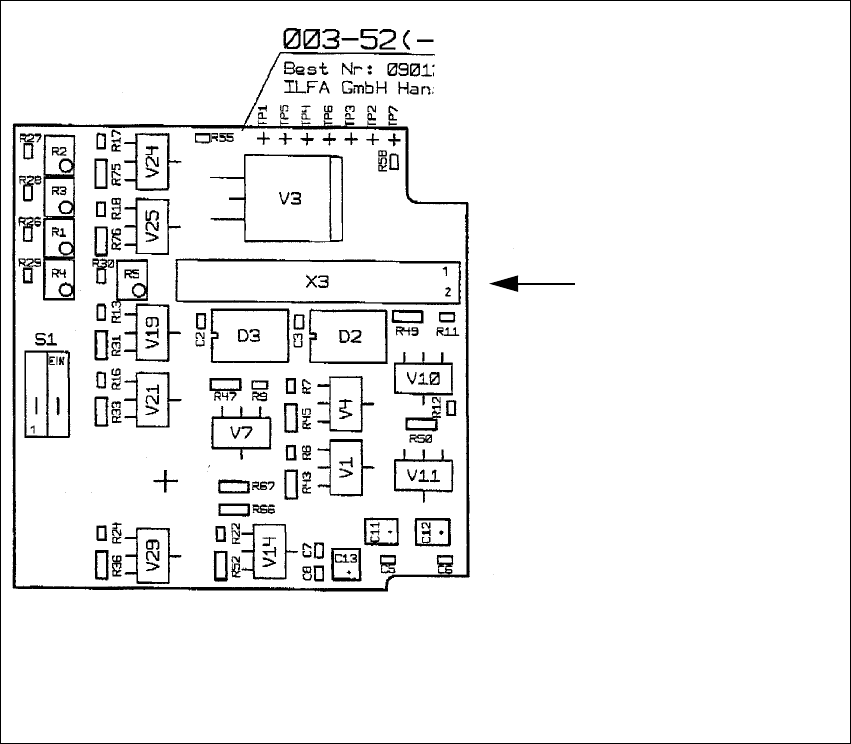
2.13.1 Layout: PCB Camera Board and Vision Board, Modular
2
Fig. 2.13.1 Layout: PCB Camera Board, Modular
Layout, component side
Cable
Illumination of the
PCB camera
Multicolor --> X3
SIPLACE F5 HM 2 Assembly Instructions PCB Camera, Multicolor SIPLACE F5 HM
05/2007 Edition 2.13 Attachments: PCBs, Cables and Circuit Diagrams
81
2
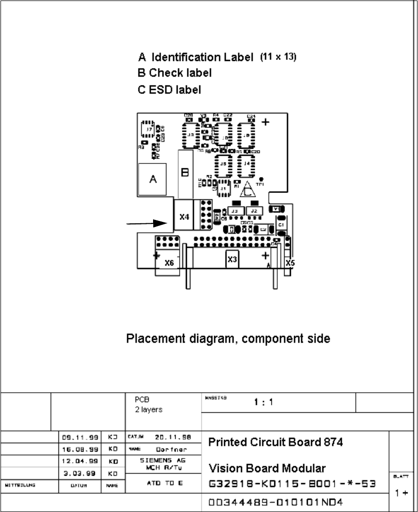
Fig. 2.13.2 Layout: Vision Board, Modular
2
2
2
2
"Camera" of the
PCB Camera Multicolor
-> X4
Cable