1_H24维修手册.pdf - 第142页
Edition 5.0 H24 Head Re pair T raining T ext for Ser v ice Enginee rs Camer a posi t ion adjus t ment, curr ent value (gr ays cale value ) a djustmen t a nd area ch ec k FK -9F50- 08-0E 1 1 -2 FU JI MACHINE MFG . CO., L …
Edition 5.0 H24 Head Repair Training Text for Service Engineers
Camera position adjustment, current value (grayscale value) adjustment and area check
FK-9F50-08-0E 11-1 FUJI MACHINE MFG. CO., LTD.
Chapter 11 - Camera Position Adjustment, Current
Value (Grayscale Value) Adjustment and Area Check
11.1 Required Jigs
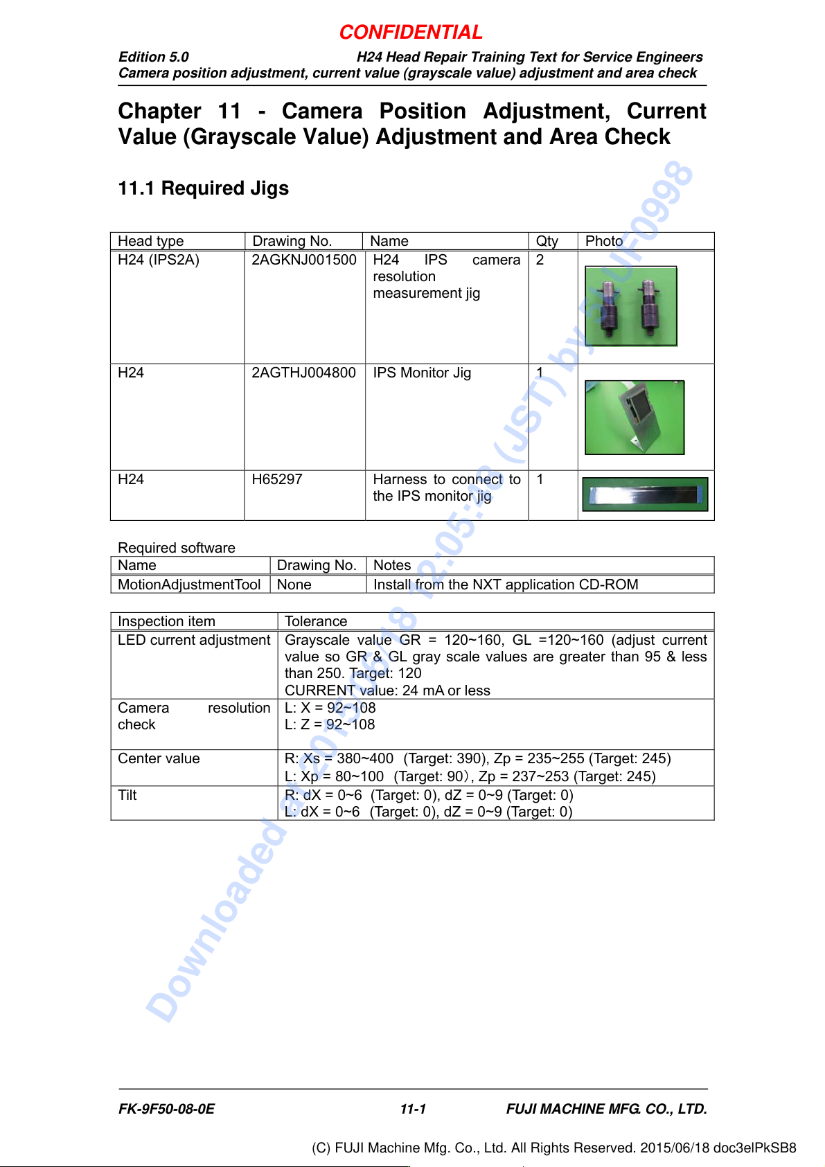
Head type Drawing No. Name Qty Photo
H24 (IPS2A) 2AGKNJ001500 H24 IPS camera
resolution
measurement jig
2
H24 2AGTHJ004800 IPS Monitor Jig 1
H24 H65297 Harness to connect to
the IPS monitor jig
1
Required software
Name Drawing No. Notes
MotionAdjustmentTool None Install from the NXT application CD-ROM
Inspection item Tolerance
LED current adjustment
Grayscale value GR = 120~160, GL =120~160 (adjust current
value so GR & GL gray scale values are greater than 95 & less
than 250. Target: 120
CURRENT value: 24 mA or less
Camera resolution
check
L: X = 92~108
L: Z = 92~108
Center value R: Xs = 380~400 (Target: 390), Zp = 235~255 (Target: 245)
L: Xp = 80~100 (Target: 90), Zp = 237~253 (Target: 245)
Tilt R: dX = 0~6 (Target: 0), dZ = 0~9 (Target: 0)
L: dX = 0~6 (Target: 0), dZ = 0~9 (Target: 0)
CONFIDENTIAL
Downloaded at 2015/06/18 12:05:48 (JST) by 5LUF0998
(C) FUJI Machine Mfg. Co., Ltd. All Rights Reserved. 2015/06/18 doc3elPkSB8
Edition 5.0 H24 Head Repair Training Text for Service Engineers
Camera position adjustment, current value (grayscale value) adjustment and area check
FK-9F50-08-0E 11-2 FUJI MACHINE MFG. CO., LTD.
11.2. Preparation On the Module
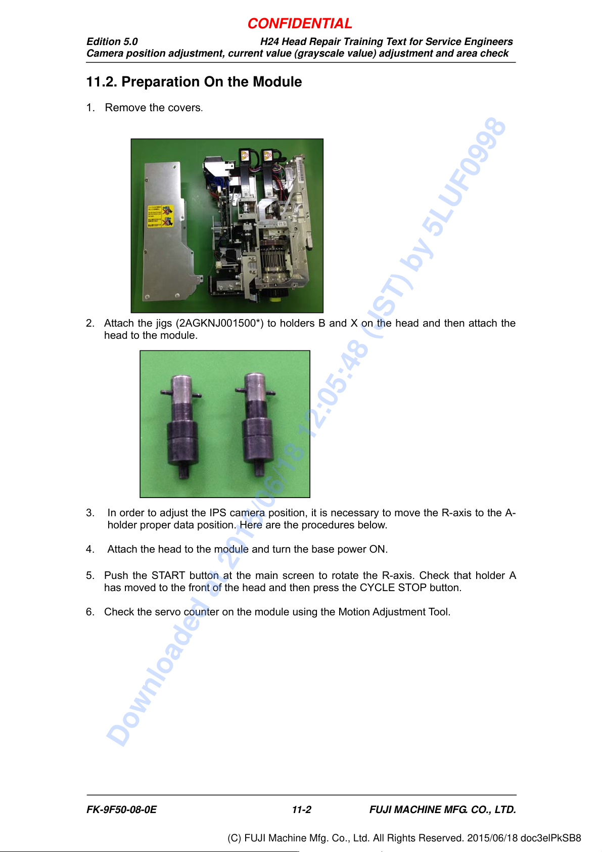
1. Remove the covers.
2. Attach the jigs (2AGKNJ001500*) to holders B and X on the head and then attach the
head to the module.
3. In order to adjust the IPS camera position, it is necessary to move the R-axis to the A-
holder proper data position. Here are the procedures below.
4. Attach the head to the module and turn the base power ON.
5. Push the START button at the main screen to rotate the R-axis. Check that holder A
has moved to the front of the head and then press the CYCLE STOP button.
6. Check the servo counter on the module using the Motion Adjustment Tool.
CONFIDENTIAL
Downloaded at 2015/06/18 12:05:48 (JST) by 5LUF0998
(C) FUJI Machine Mfg. Co., Ltd. All Rights Reserved. 2015/06/18 doc3elPkSB8
Edition 5.0 H24 Head Repair Training Text for Service Engineers
Camera position adjustment, current value (grayscale value) adjustment and area check
FK-9F50-08-0E 11-3 FUJI MACHINE MFG. CO., LTD.
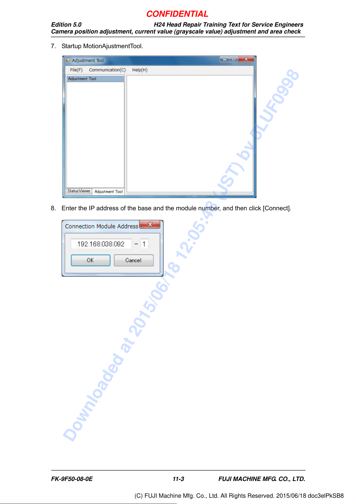
7. Startup MotionAjustmentTool.
8. Enter the IP address of the base and the module number, and then click [Connect].
CONFIDENTIAL
Downloaded at 2015/06/18 12:05:48 (JST) by 5LUF0998
(C) FUJI Machine Mfg. Co., Ltd. All Rights Reserved. 2015/06/18 doc3elPkSB8