1_H24维修手册.pdf - 第207页
E d i ti o n 5 . 0 H 24 H ead R ep ai r T r ai n i n g T ext f o r S er vi ce E n g i n e e r s I PS C a m e r a p o s i ti o n a d j u s tm e n t fo r H 2 4 h e a d u s i n g h e a d b e n c h 5. I n t he “ A D J U S T …
Edition 5.0 H24 Head Repair Training Text for Service Engineers
IPS Camera position adjustment for H24 head using head bench
2.7 Checking the Field of Vision
External light can influence the results, so be sure to perform the procedure in a shaded
area.
1. Attach the jig nozzles (2AGKNJ001500) to syringe B and X.
2. While checking the R-axis servo count in Head bench R-axis servo counter, move the
A holder to the front of the head manually or use the “Move (absolute pos)” button.
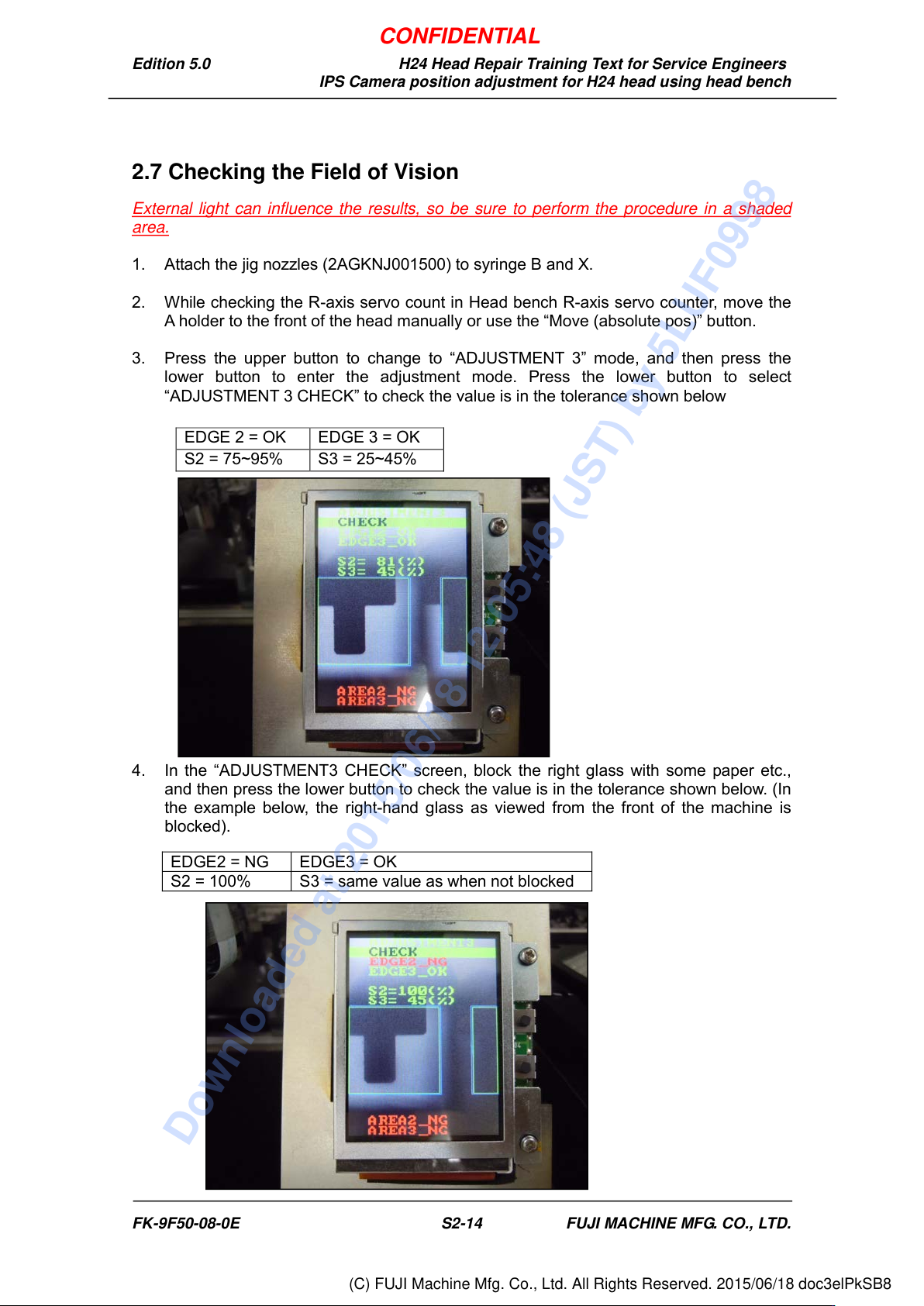
3. Press the upper button to change to “ADJUSTMENT 3” mode, and then press the
lower button to enter the adjustment mode. Press the lower button to select
“ADJUSTMENT 3 CHECK” to check the value is in the tolerance shown below
4. In the “ADJUSTMENT3 CHECK” screen, block the right glass with some paper etc.,
and then press the lower button to check the value is in the tolerance shown below. (In
the example below, the right-hand glass as viewed from the front of the machine is
blocked).
EDGE 2 = OK
EDGE 3 = OK
S2 = 75~95%
S3 = 25~45%
EDGE2 = NG
EDGE3 = OK
S2 = 100%
S3 = same value as when not blocked
FK-9F50-08-0E S2-14 FUJI MACHINE MFG. CO., LTD.
CONFIDENTIAL
Downloaded at 2015/06/18 12:05:48 (JST) by 5LUF0998
(C) FUJI Machine Mfg. Co., Ltd. All Rights Reserved. 2015/06/18 doc3elPkSB8
Edition 5.0 H24 Head Repair Training Text for Service Engineers
IPS Camera position adjustment for H24 head using head bench
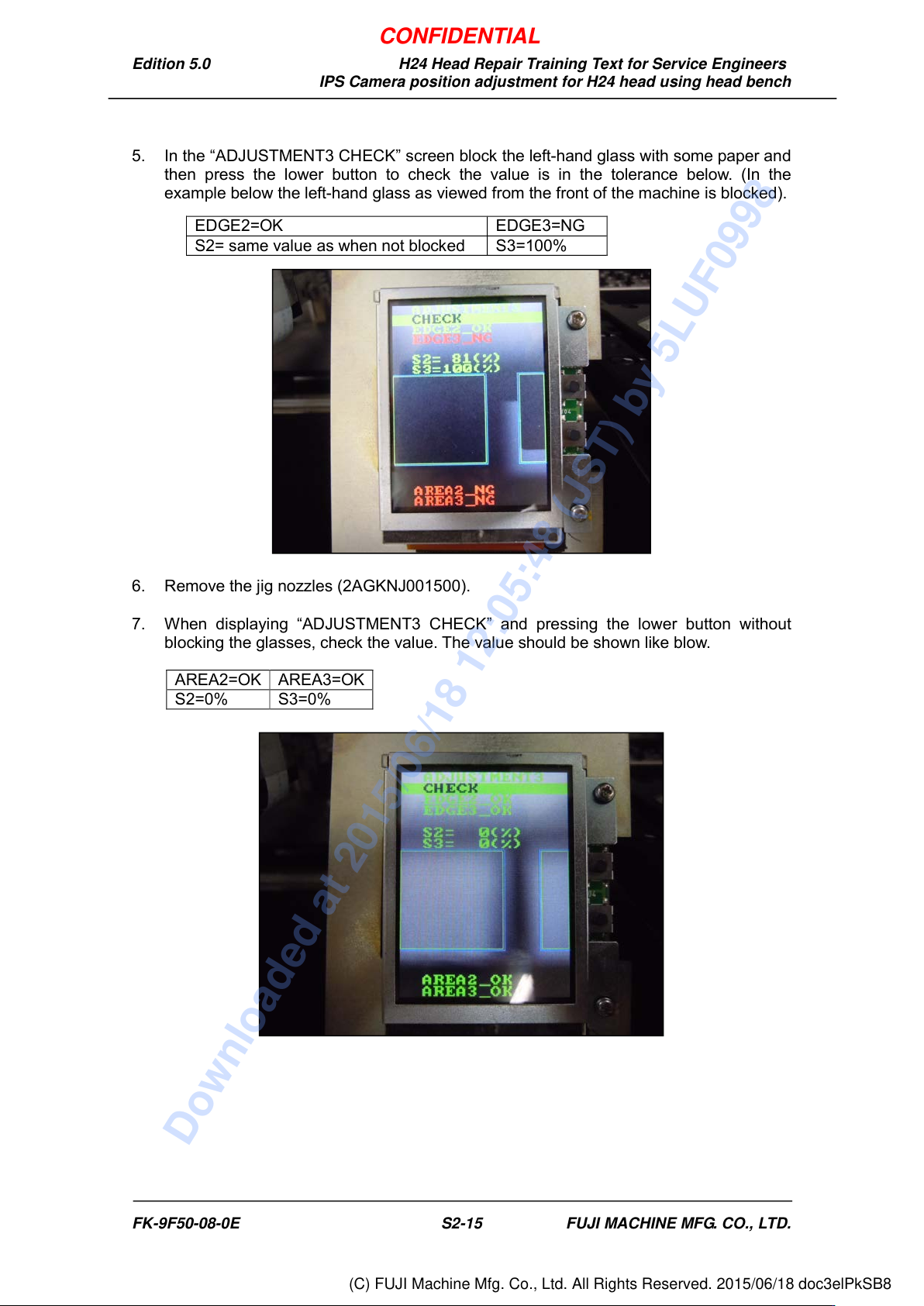
5. In the “ADJUSTMENT3 CHECK” screen block the left-hand glass with some paper and
then press the lower button to check the value is in the tolerance below. (In the
example below the left-hand glass as viewed from the front of the machine is blocked).
6. Remove the jig nozzles (2AGKNJ001500).
7. When displaying “ADJUSTMENT3 CHECK” and pressing the lower button without
blocking the glasses, check the value. The value should be shown like blow.
EDGE2=OK
EDGE3=NG
S2= same value as when not blocked
S3=100%
AREA2=OK
AREA3=OK
S2=0%
S3=0%
FK-9F50-08-0E S2-15 FUJI MACHINE MFG. CO., LTD.
CONFIDENTIAL
Downloaded at 2015/06/18 12:05:48 (JST) by 5LUF0998
(C) FUJI Machine Mfg. Co., Ltd. All Rights Reserved. 2015/06/18 doc3elPkSB8
Edition 5.0 H24 Head Repair Training Text for Service Engineers
IPS Camera position adjustment for H24 head using head bench
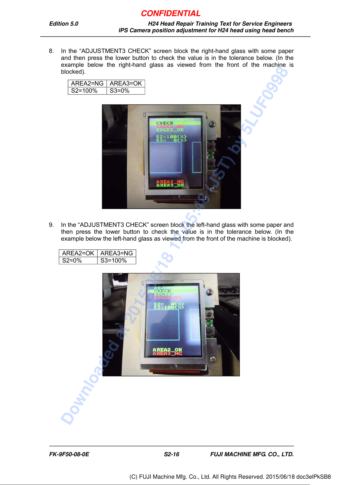
8. In the “ADJUSTMENT3 CHECK” screen block the right-hand glass with some paper
and then press the lower button to check the value is in the tolerance below. (In the
example below the right-hand glass as viewed from the front of the machine is
blocked).
9. In the “ADJUSTMENT3 CHECK” screen block the left-hand glass with some paper and
then press the lower button to check the value is in the tolerance below. (In the
example below the left-hand glass as viewed from the front of the machine is blocked).
AREA2=NG
AREA3=OK
S2=100%
S3=0%
AREA2=OK
AREA3=NG
S2=0%
S3=100%
FK-9F50-08-0E S2-16 FUJI MACHINE MFG. CO., LTD.
CONFIDENTIAL
Downloaded at 2015/06/18 12:05:48 (JST) by 5LUF0998
(C) FUJI Machine Mfg. Co., Ltd. All Rights Reserved. 2015/06/18 doc3elPkSB8