1_H24维修手册.pdf - 第41页
E d i ti o n 5 .0 H 24 H ead R ep ai r T r ai n i n g T ext f o r S er vi ce E n g i n e e r s R ep l aci n g th e Z - axi s b al l scr ew 8. R e m ov e t he s t eppi ng m ot or f r o m t he he ad. 9. R e m ov e t he s t…
Edition 5.0 H24 Head Repair Training Text for Service Engineers
Replacing the Z-axis ball screw
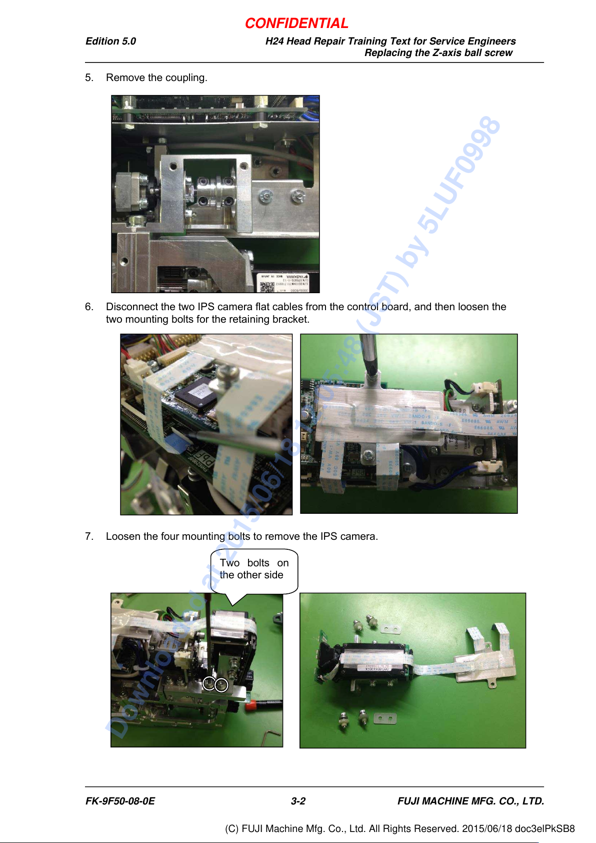
5. Remove the coupling.
6. Disconnect the two IPS camera flat cables from the control board, and then loosen the
two mounting bolts for the retaining bracket.
7. Loosen the four mounting bolts to remove the IPS camera.
Two
bolts on
the other side
FK-9F50-08-0E
3-2
FUJI MACHINE MFG. CO., LTD.
CONFIDENTIAL
Downloaded at 2015/06/18 12:05:48 (JST) by 5LUF0998
(C) FUJI Machine Mfg. Co., Ltd. All Rights Reserved. 2015/06/18 doc3elPkSB8
Edition 5.0 H24 Head Repair Training Text for Service Engineers
Replacing the Z-axis ball screw
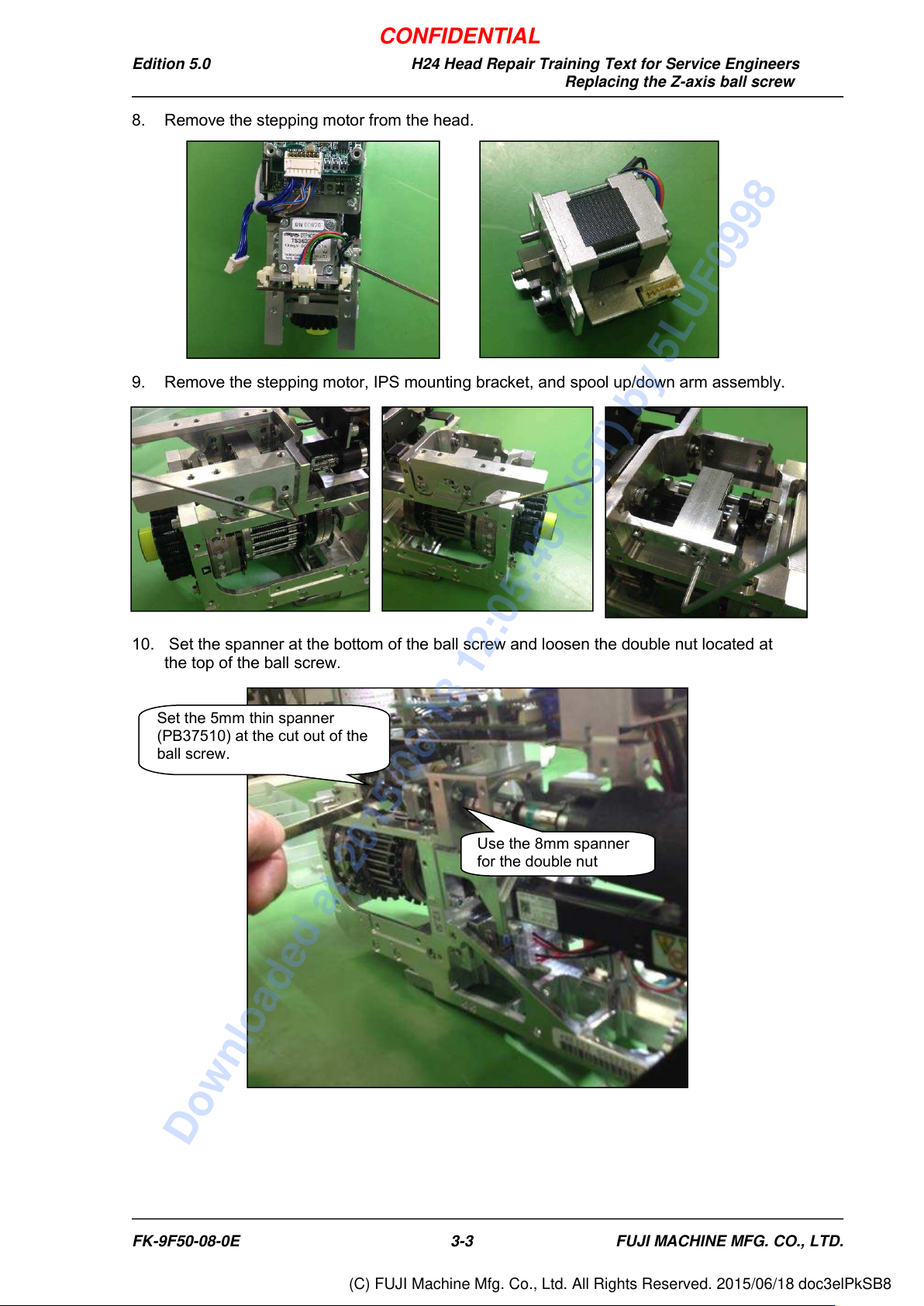
8. Remove the stepping motor from the head.
9. Remove the stepping motor, IPS mounting bracket, and spool up/down arm assembly.
10. Set the spanner at the bottom of the ball screw and loosen the double nut located at
the top of the ball screw.
Set the 5mm thin spanner
(PB37510) at the cut out of the
ball screw.
Use the 8mm spanner
for the double nut
FK-9F50-08-0E
3-3
FUJI MACHINE MFG. CO., LTD.
CONFIDENTIAL
Downloaded at 2015/06/18 12:05:48 (JST) by 5LUF0998
(C) FUJI Machine Mfg. Co., Ltd. All Rights Reserved. 2015/06/18 doc3elPkSB8
Edition 5.0 H24 Head Repair Training Text for Service Engineers
Replacing the Z-axis ball screw
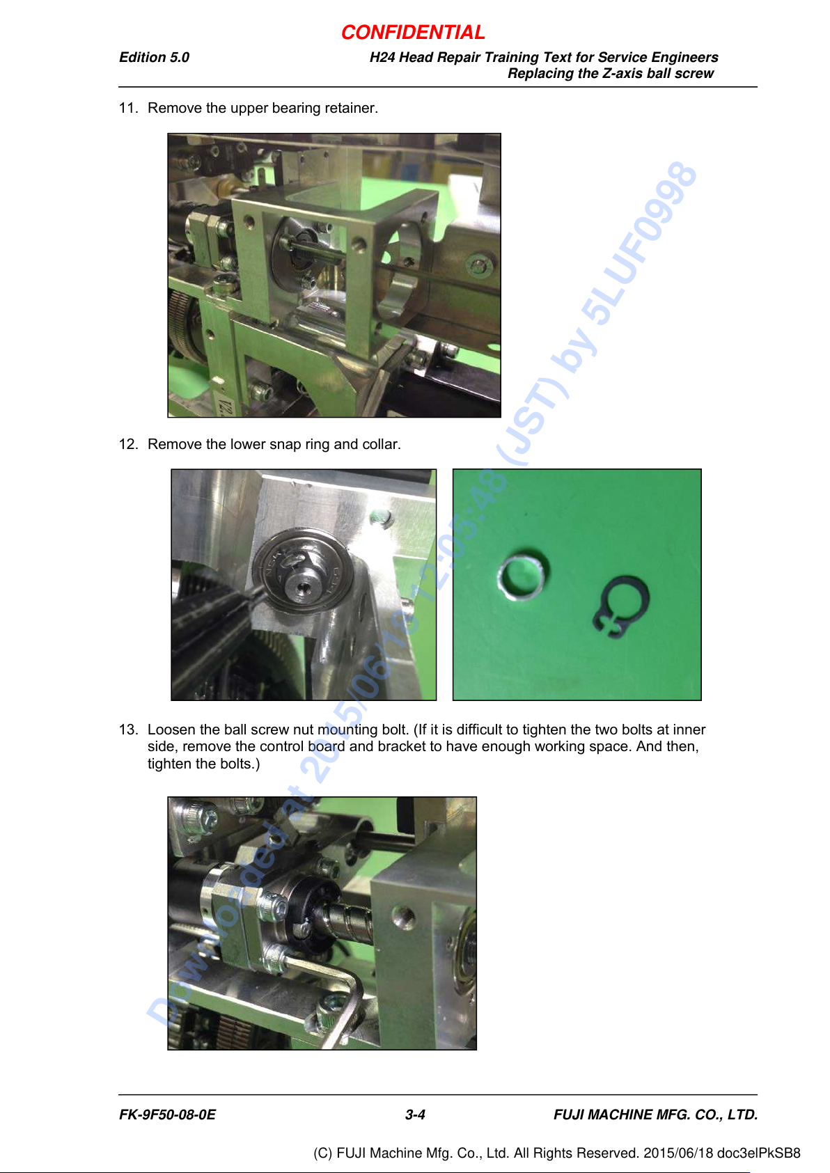
11. Remove the upper bearing retainer.
12. Remove the lower snap ring and collar.
13. Loosen the ball screw nut mounting bolt. (If it is difficult to tighten the two bolts at inner
side, remove the control board and bracket to have enough working space. And then,
tighten the bolts.)
FK-9F50-08-0E
3-4
FUJI MACHINE MFG. CO., LTD.
CONFIDENTIAL
Downloaded at 2015/06/18 12:05:48 (JST) by 5LUF0998
(C) FUJI Machine Mfg. Co., Ltd. All Rights Reserved. 2015/06/18 doc3elPkSB8