1_H24维修手册.pdf - 第11页
E d i ti o n 5 .0 H 24 H ead R ep ai r T r ai n i n g T ext f o r S er vi ce E n g i n e e r s CO NT E NT S C O N TE N TS Cha pt e r 1 - Re pl a c i ng t he s y r i nge s 1 .1 R em ov i ng t he ol d s y r i n ge ........…
Edition 5.0 H24 Head Repair Training Text for Service Engineers
MEMO:
FK-9F50-08-0E FUJI MACHINE MFG. CO., LTD.
CONFIDENTIAL
Downloaded at 2015/06/18 12:05:48 (JST) by 5LUF0998
(C) FUJI Machine Mfg. Co., Ltd. All Rights Reserved. 2015/06/18 doc3elPkSB8
Edition 5.0 H24 Head Repair Training Text for Service Engineers
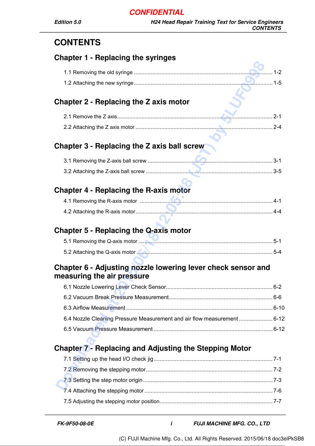
CONTENTS
CONTENTS
Chapter 1 - Replacing the syringes
1.1
Removing the old syringe ........................................................................................... 1-2
1.2
Attaching the new syringe ........................................................................................... 1-5
Chapter 2 - Replacing the Z axis motor
2.1
Remove the Z axis ...................................................................................................... 2-1
2.2
Attaching the Z axis motor .......................................................................................... 2-4
Chapter 3 - Replacing the Z axis ball screw
3.1
Removing the Z-axis ball screw .................................................................................. 3-1
3.2
Attaching the Z-axis ball screw ................................................................................... 3-5
Chapter 4 - Replacing the R-axis motor
4.1 Removing the R-axis motor ....................................................................................... 4-1
4.2
Attaching the R-axis motor .......................................................................................... 4-4
Chapter 5 - Replacing the Q-axis motor
5.1 Removing the Q-axis motor ........................................................................................ 5-1
5.2
Attaching the Q-axis motor ......................................................................................... 5-4
Chapter 6 - Adjusting nozzle lowering lever check sensor and
measuring the air pressure
6.1 Nozzle Lowering Lever Check Sensor ...................................................................... 6-2
6.2 Vacuum Break Pressure Measurement .................................................................... 6-6
6.3 Airflow Measurement ................................................................................................ 6-10
6.4 Nozzle Cleaning Pressure Measurement and air flow measurement ...................... 6-12
6.5 Vacuum Pressure Measurement .............................................................................. 6-12
Chapter 7 - Replacing and Adjusting the Stepping Motor
7.1 Setting up the head I/O check jig .............................................................................. 7-1
7.2 Removing the stepping motor ................................................................................... 7-2
7.3 Setting the step motor origin ..................................................................................... 7-3
7.4 Attaching the stepping motor .................................................................................... 7-6
7.5
Adjusting the stepping motor position .......................................................................... 7-7
FK-9F50-08-0E i FUJI MACHINE MFG. CO., LTD
CONFIDENTIAL
Downloaded at 2015/06/18 12:05:48 (JST) by 5LUF0998
(C) FUJI Machine Mfg. Co., Ltd. All Rights Reserved. 2015/06/18 doc3elPkSB8
Edition 5.0 H24 Head Repair Training Text for Service Engineers
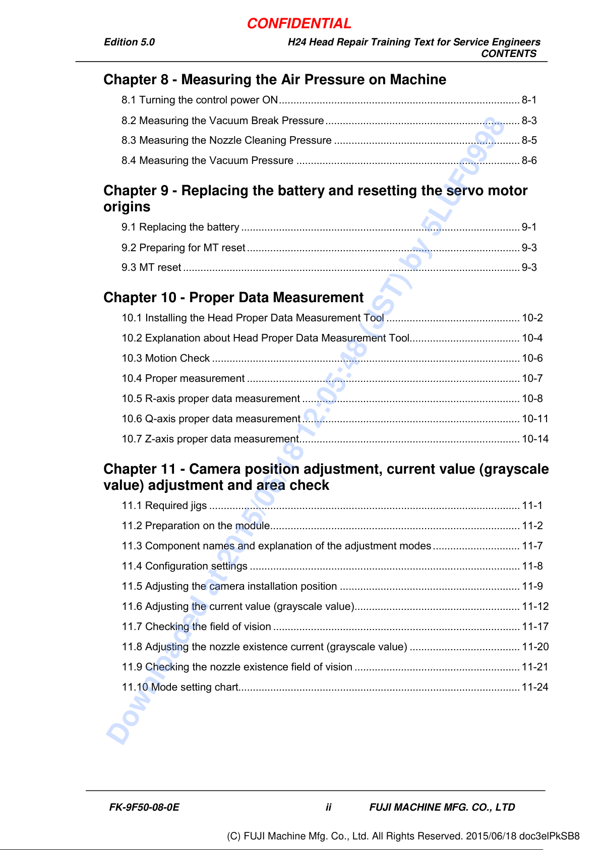
CONTENTS
Chapter 8 - Measuring the Air Pressure on Machine
8.1 Turning the control power ON ................................................................................... 8-1
8.2 Measuring the Vacuum Break Pressure ................................................................... 8-3
8.3 Measuring the Nozzle Cleaning Pressure ................................................................ 8-5
8.4 Measuring the Vacuum Pressure ............................................................................. 8-6
Chapter 9 - Replacing the battery and resetting the servo motor
origins
9.1 Replacing the battery ................................................................................................ 9-1
9.2 Preparing for MT reset .............................................................................................. 9-3
9.3 MT reset .................................................................................................................... 9-3
Chapter 10 - Proper Data Measurement
10.1 Installing the Head Proper Data Measurement Tool .............................................. 10-2
10.2 Explanation about Head Proper Data Measurement Tool...................................... 10-4
10.3 Motion Check .......................................................................................................... 10-6
10.4 Proper measurement .............................................................................................. 10-7
10.5 R-axis proper data measurement ........................................................................... 10-8
10.6 Q-axis proper data measurement ........................................................................... 10-11
10.7 Z-axis proper data measurement ............................................................................ 10-14
Chapter 11 - Camera position adjustment, current value (grayscale
value) adjustment and area check
11.1 Required jigs ........................................................................................................... 11-1
11.2 Preparation on the module ...................................................................................... 11-2
11.3 Component names and explanation of the adjustment modes .............................. 11-7
11.4 Configuration settings ............................................................................................. 11-8
11.5 Adjusting the camera installation position .............................................................. 11-9
11.6 Adjusting the current value (grayscale value) ......................................................... 11-12
11.7 Checking the field of vision ..................................................................................... 11-17
11.8 Adjusting the nozzle existence current (grayscale value) ...................................... 11-20
11.9 Checking the nozzle existence field of vision ......................................................... 11-21
11.10 Mode setting chart................................................................................................. 11-24
FK-9F50-08-0E ii FUJI MACHINE MFG. CO., LTD
CONFIDENTIAL
Downloaded at 2015/06/18 12:05:48 (JST) by 5LUF0998
(C) FUJI Machine Mfg. Co., Ltd. All Rights Reserved. 2015/06/18 doc3elPkSB8