1_H24维修手册.pdf - 第126页
E d it io n 5 .0 H 24 H ead R ep ai r T r ai n i n g T ext f o r S er vi ce E n g i n e e r Pro p e r D at a M e asu r em en t 10 . 5 R - a x i s P r ope r D a t a M e as u r e m e n t 1. T ur n t he pow er O N i n t he …
Edition 5.0 H24 Head Repair Training Text for Service Engineer
Proper Data Measurement
10.4 Proper Measurement
Note: It is necessary to reset the “Encoder Backup Alarm” in order to start the proper
measurement. Procedure: Use “Motion Adjustment Tool”, and then release the encoder
backup alarm by executing MT-reset. (Refer to chapters 9.3 and 9.4 for the detailed MT-
reset procedure.)
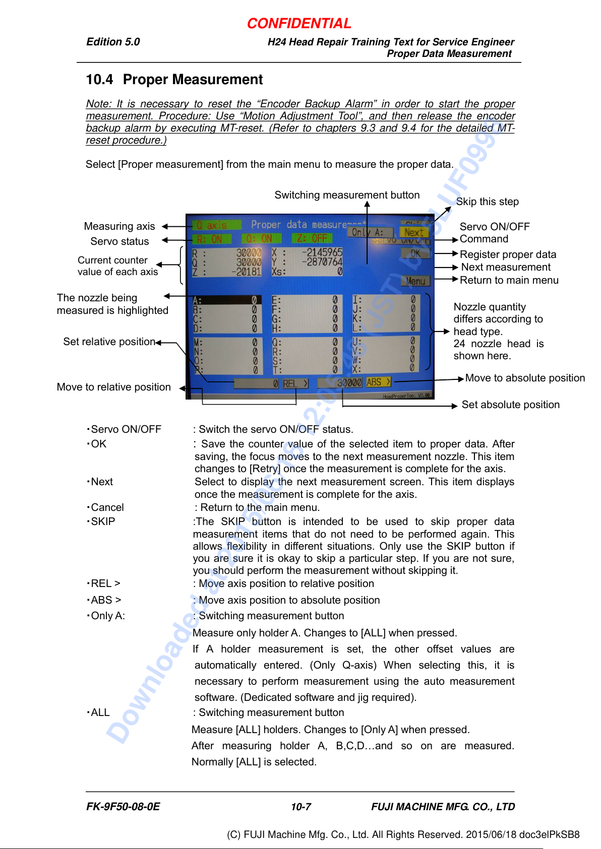
Select [Proper measurement] from the main menu to measure the proper data.
・Servo ON/OFF : Switch the servo ON/OFF status.
・OK
: Save the counter value of the selected item to proper data. After
saving, the focus moves to the next measurement nozzle. This item
changes to [Retry] once the measurement is complete for the axis.
・Next Select to display the next measurement screen. This item displays
once the measurement is complete for the axis.
・Cancel : Return to the main menu.
・SKIP :The SKIP button is intended to be used to skip proper data
measurement items that do not need to be performed again. This
allows flexibility in different situations. Only use the SKIP button if
you are sure it is okay to skip a particular step. If you are not sure,
you should perform the measurement without skipping it.
・REL > : Move axis position to relative position
・ABS > : Move axis position to absolute position
・Only A: : Switching measurement button
Measure only holder A. Changes to [ALL] when pressed.
If A holder measurement is set, the other offset values are
automatically entered. (Only Q-axis) When selecting this, it is
necessary to perform measurement using the auto measurement
software. (Dedicated software and jig required).
・ALL : Switching measurement button
Measure [ALL] holders. Changes to [Only A] when pressed.
After measuring holder A, B,C,D…and so on are measured.
Normally [ALL] is selected.
Skip this step
The nozzle being
measured is highlighted
Return to main menu
Nozzle quantity
differs according to
head type.
24 nozzle head is
shown here.
Register proper data
Current counter
value of each axis
Next measurement
Servo ON/OFF
Command
Measuring axis
Move to absolute position
Move to relative position
Set absolute position
Switching measurement button
Set relative position
Servo status
FK-9F50-08-0E 10-7 FUJI MACHINE MFG. CO., LTD
CONFIDENTIAL
Downloaded at 2015/06/18 12:05:48 (JST) by 5LUF0998
(C) FUJI Machine Mfg. Co., Ltd. All Rights Reserved. 2015/06/18 doc3elPkSB8
Edition 5.0 H24 Head Repair Training Text for Service Engineer
Proper Data Measurement
10.5 R-axis Proper Data Measurement
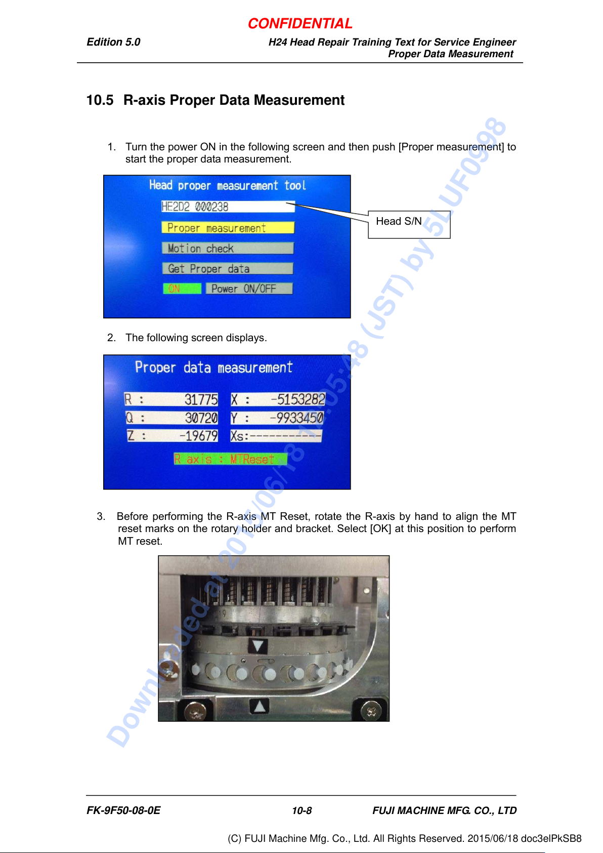
1. Turn the power ON in the following screen and then push [Proper measurement] to
start the proper data measurement.
2. The following screen displays.
3. Before performing the R-axis MT Reset, rotate the R-axis by hand to align the MT
reset marks on the rotary holder and bracket. Select [OK] at this position to perform
MT reset.
Head S/N
FK-9F50-08-0E 10-8 FUJI MACHINE MFG. CO., LTD
CONFIDENTIAL
Downloaded at 2015/06/18 12:05:48 (JST) by 5LUF0998
(C) FUJI Machine Mfg. Co., Ltd. All Rights Reserved. 2015/06/18 doc3elPkSB8
Edition 5.0 H24 Head Repair Training Text for Service Engineer
Proper Data Measurement
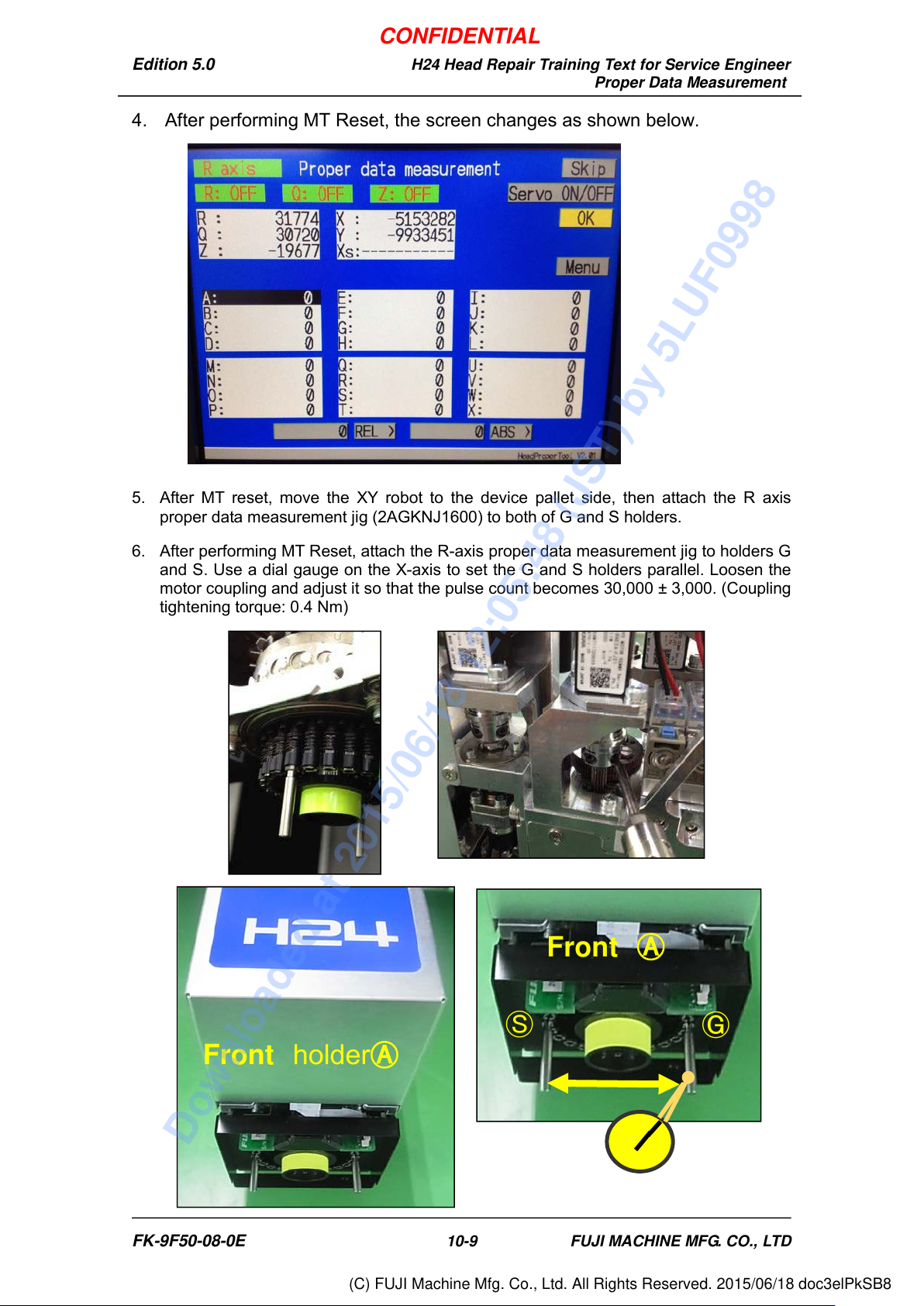
4. After performing MT Reset, the screen changes as shown below.
5. After MT reset, move the XY robot to the device pallet side, then attach the R axis
proper data measurement jig (2AGKNJ1600) to both of G and S holders.
6. After performing MT Reset, attach the R-axis proper data measurement jig to holders G
and S. Use a dial gauge on the X-axis to set the G and S holders parallel. Loosen the
motor coupling and adjust it so that the pulse count becomes 30,000 ± 3,000. (Coupling
tightening torque: 0.4 Nm)
Front holderⒶ
Front Ⓐ
Ⓖ
Ⓢ
FK-9F50-08-0E 10-9 FUJI MACHINE MFG. CO., LTD
CONFIDENTIAL
Downloaded at 2015/06/18 12:05:48 (JST) by 5LUF0998
(C) FUJI Machine Mfg. Co., Ltd. All Rights Reserved. 2015/06/18 doc3elPkSB8