1_H24维修手册.pdf - 第132页
E d it io n 5 .0 H 24 H ead R ep ai r T r ai n i n g T ext f o r S er vi ce E n g i n e e r Pro p e r D at a M e asu r em en t 10 . 7 Z - a xi s P r o p er D a t a M e as u r e m e n t 1. P er f or m M T r es et at t h e…
Edition 5.0 H24 Head Repair Training Text for Service Engineer
Proper Data Measurement
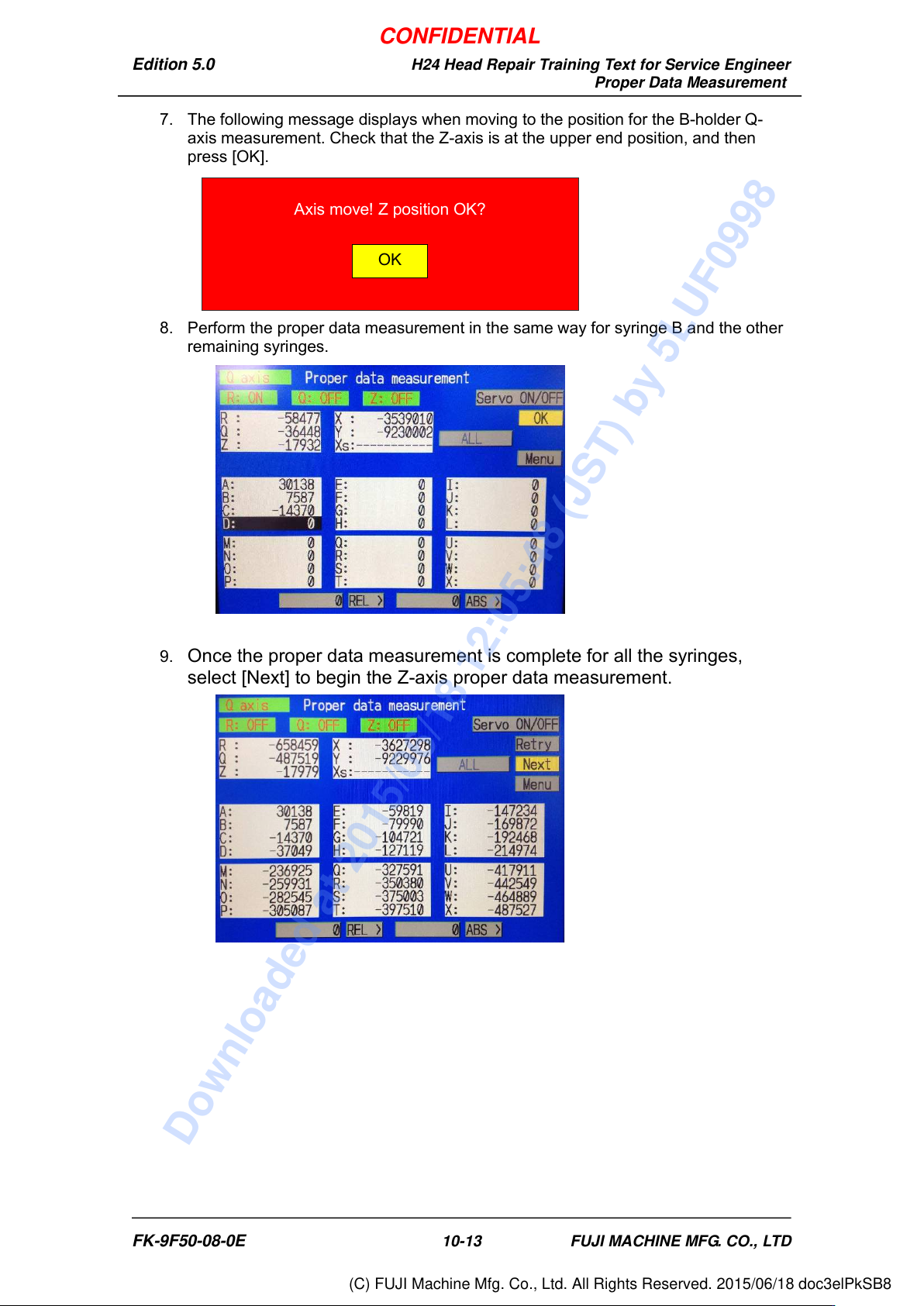
7. The following message displays when moving to the position for the B-holder Q-
axis measurement. Check that the Z-axis is at the upper end position, and then
press [OK].
8. Perform the proper data measurement in the same way for syringe B and the other
remaining syringes.
9.
Once the proper data measurement is complete for all the syringes,
select [Next] to begin the Z-axis proper data measurement.
Axis move! Z position OK?
OK
FK-9F50-08-0E 10-13 FUJI MACHINE MFG. CO., LTD
CONFIDENTIAL
Downloaded at 2015/06/18 12:05:48 (JST) by 5LUF0998
(C) FUJI Machine Mfg. Co., Ltd. All Rights Reserved. 2015/06/18 doc3elPkSB8
Edition 5.0 H24 Head Repair Training Text for Service Engineer
Proper Data Measurement
10.7 Z-axis Proper Data Measurement
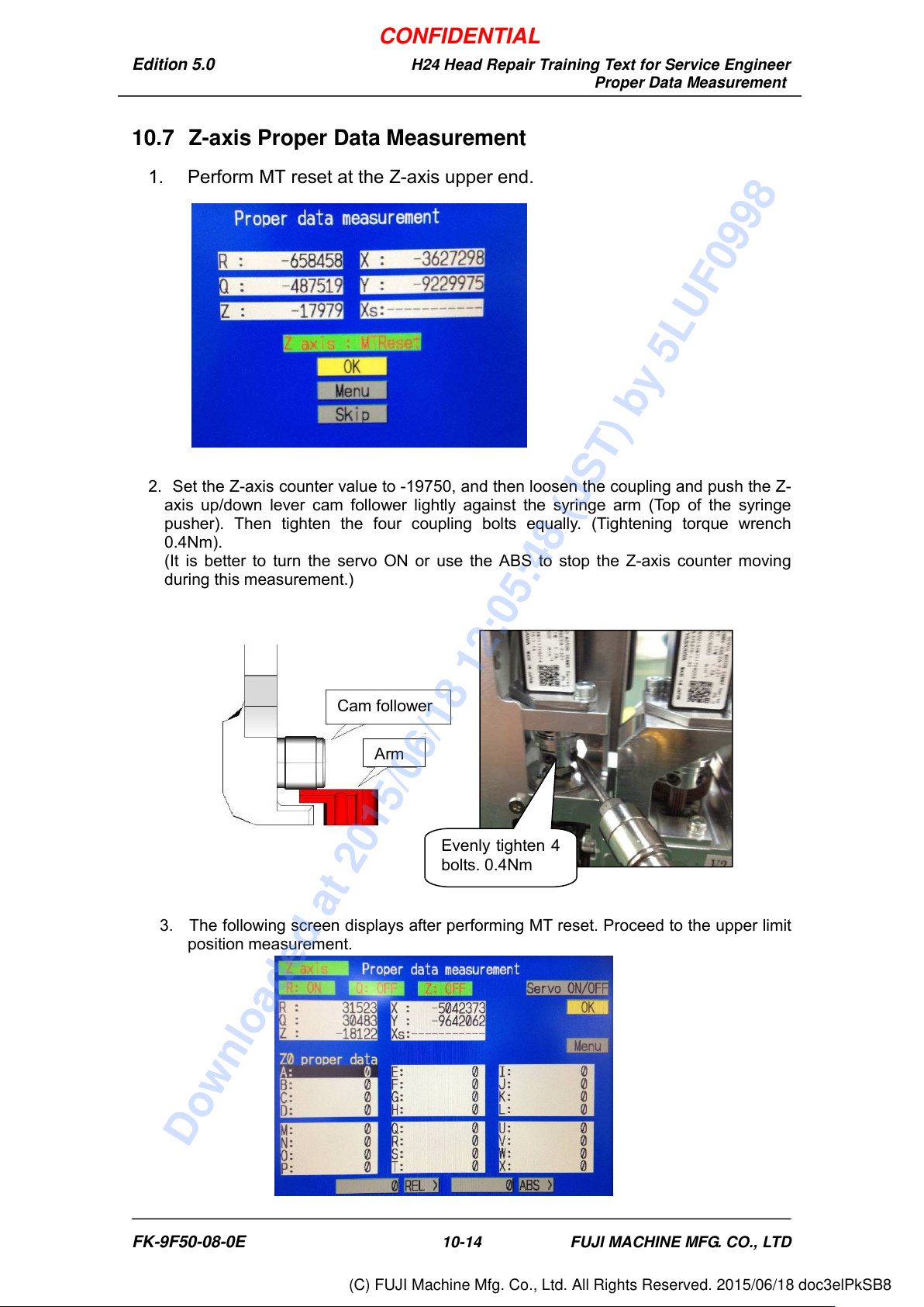
1. Perform MT reset at the Z-axis upper end.
2. Set the Z-axis counter value to -19750, and then loosen the coupling and push the Z-
axis up/down lever cam follower lightly against the syringe arm (Top of the syringe
pusher). Then tighten the four coupling bolts equally. (Tightening torque wrench
0.4Nm).
(It is better to turn the servo ON or use the ABS to stop the Z-axis counter moving
during this measurement.)
3. The following screen displays after performing MT reset. Proceed to the upper limit
position measurement.
Evenly tighten 4
bolts. 0.4Nm
Cam follower
Arm
FK-9F50-08-0E 10-14 FUJI MACHINE MFG. CO., LTD
CONFIDENTIAL
Downloaded at 2015/06/18 12:05:48 (JST) by 5LUF0998
(C) FUJI Machine Mfg. Co., Ltd. All Rights Reserved. 2015/06/18 doc3elPkSB8
Edition 5.0 H24 Head Repair Training Text for Service Engineer
Proper Data Measurement
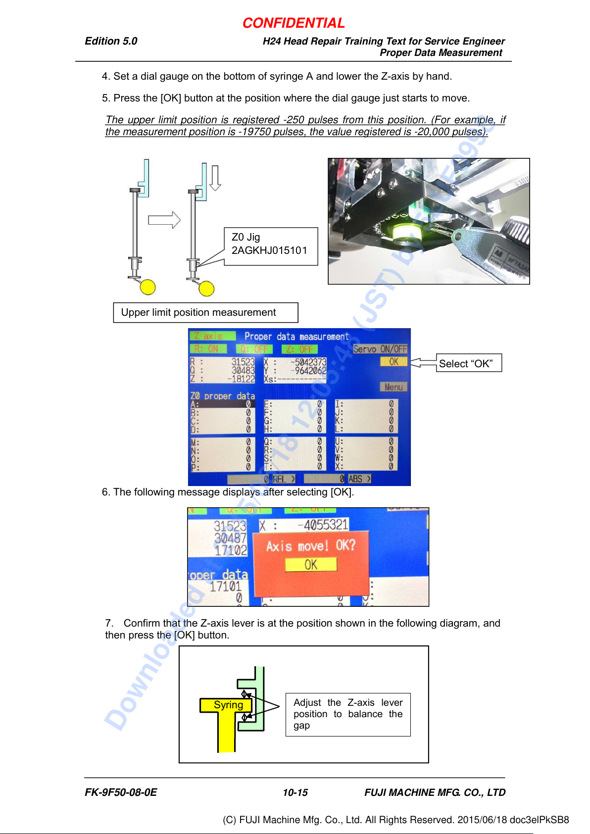
4. Set a dial gauge on the bottom of syringe A and lower the Z-axis by hand.
5. Press the [OK] button at the position where the dial gauge just starts to move.
The upper limit position is registered -250 pulses from this position. (For example, if
the measurement position is -19750 pulses, the value registered is -20,000 pulses).
6. The following message displays after selecting [OK].
7. Confirm that the Z-axis lever is at the position shown in the following diagram, and
then press the [OK] button.
Adjust the Z-axis lever
position to balance the
gap
Syring
Select “OK”
Z0 Jig
2AGKHJ015101
Upper limit position measurement
FK-9F50-08-0E 10-15 FUJI MACHINE MFG. CO., LTD
CONFIDENTIAL
Downloaded at 2015/06/18 12:05:48 (JST) by 5LUF0998
(C) FUJI Machine Mfg. Co., Ltd. All Rights Reserved. 2015/06/18 doc3elPkSB8