1_H24维修手册.pdf - 第136页
E d it io n 5 .0 H 24 H ead R ep ai r T r ai n i n g T ext f o r S er vi ce E n g i n e e r Pro p e r D at a M e asu r em en t 17. A fte r th e Z - ax i s up per en d and m eas ur e m e nt i s c o m pl et e d, a “ H ea d…
Edition 5.0 H24 Head Repair Training Text for Service Engineer
Proper Data Measurement
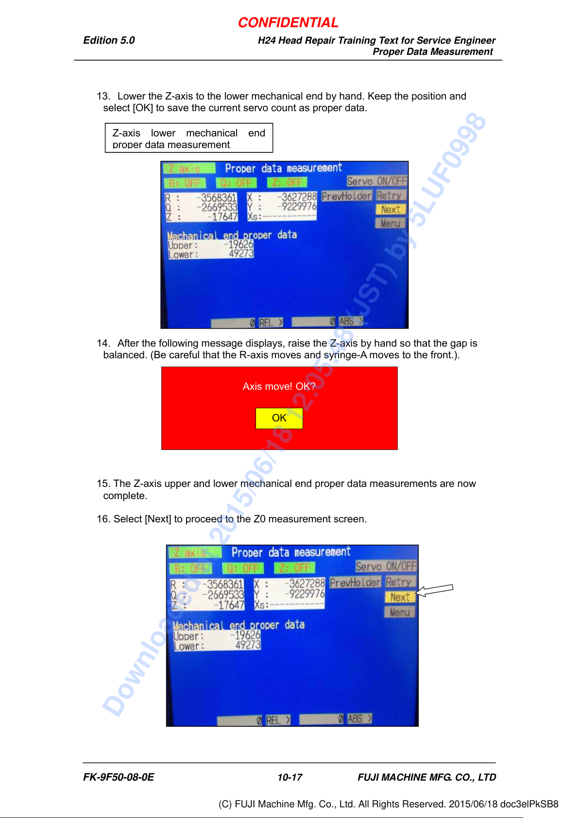
13. Lower the Z-axis to the lower mechanical end by hand. Keep the position and
select [OK] to save the current servo count as proper data.
14. After the following message displays, raise the Z-axis by hand so that the gap is
balanced. (Be careful that the R-axis moves and syringe-A moves to the front.).
15. The Z-axis upper and lower mechanical end proper data measurements are now
complete.
16. Select [Next] to proceed to the Z0 measurement screen.
Axis move! OK?
OK
Z-axis lower mechanical end
proper data measurement
FK-9F50-08-0E 10-17 FUJI MACHINE MFG. CO., LTD
CONFIDENTIAL
Downloaded at 2015/06/18 12:05:48 (JST) by 5LUF0998
(C) FUJI Machine Mfg. Co., Ltd. All Rights Reserved. 2015/06/18 doc3elPkSB8
Edition 5.0 H24 Head Repair Training Text for Service Engineer
Proper Data Measurement
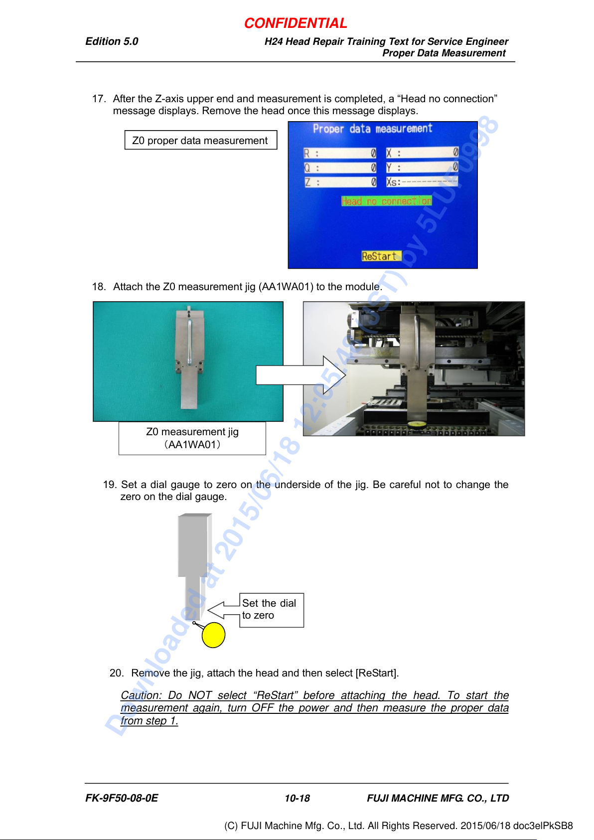
17. After the Z-axis upper end and measurement is completed, a “Head no connection”
message displays. Remove the head once this message displays.
18. Attach the Z0 measurement jig (AA1WA01) to the module.
19. Set a dial gauge to zero on the underside of the jig. Be careful not to change the
zero on the dial gauge.
20. Remove the jig, attach the head and then select [ReStart].
Caution: Do NOT select “ReStart” before attaching the head. To start the
measurement again, turn OFF the power and then measure the proper data
from step 1.
Set the dial
to zero
Z0 measurement jig
(
AA1WA01
)
Z0 proper data measurement
FK-9F50-08-0E 10-18 FUJI MACHINE MFG. CO., LTD
CONFIDENTIAL
Downloaded at 2015/06/18 12:05:48 (JST) by 5LUF0998
(C) FUJI Machine Mfg. Co., Ltd. All Rights Reserved. 2015/06/18 doc3elPkSB8
Edition 5.0 H24 Head Repair Training Text for Service Engineer
Proper Data Measurement
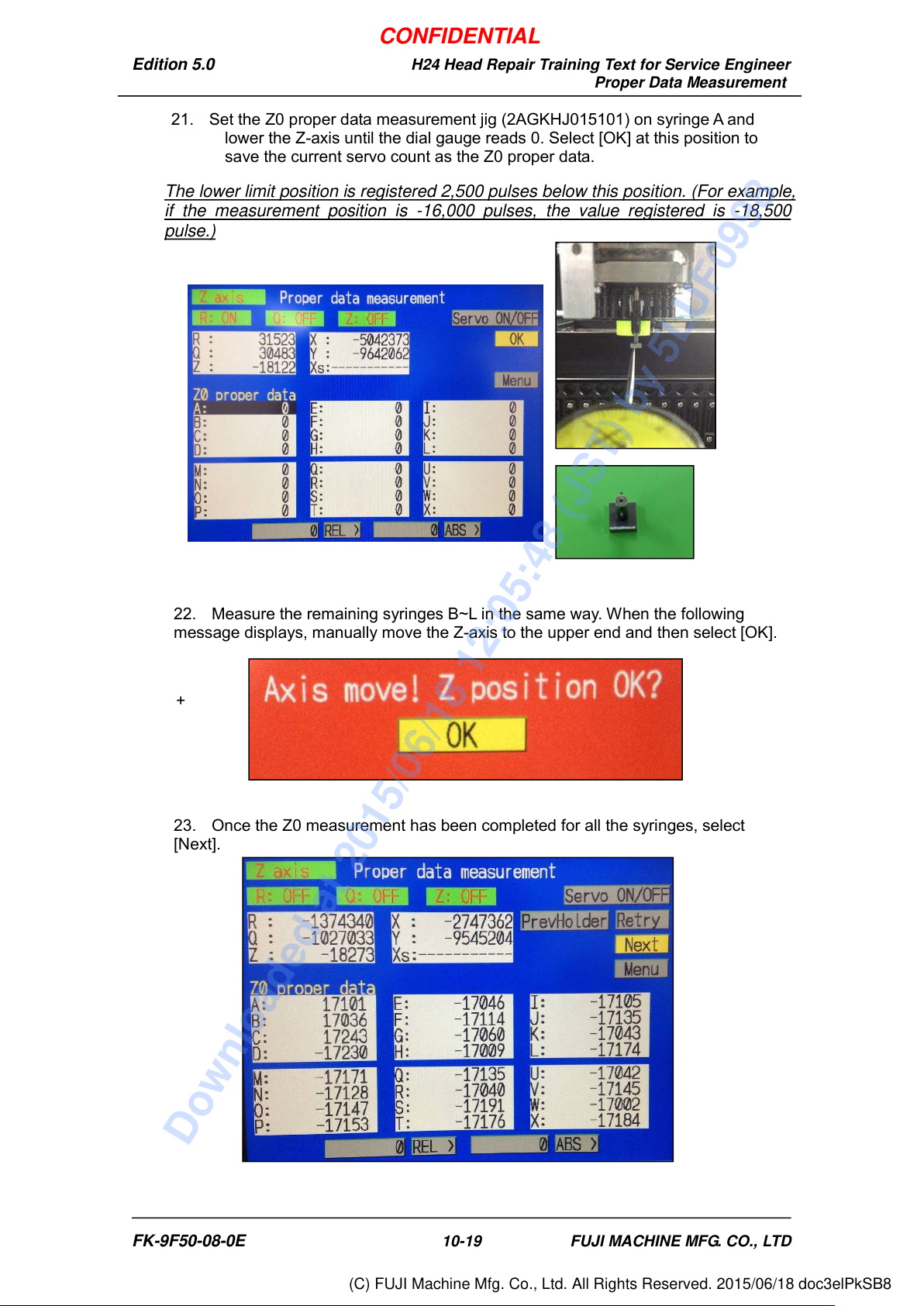
21. Set the Z0 proper data measurement jig (2AGKHJ015101) on syringe A and
lower the Z-axis until the dial gauge reads 0. Select [OK] at this position to
save the current servo count as the Z0 proper data.
The lower limit position is registered 2,500 pulses below this position. (For example,
if the measurement position is -16,000 pulses, the value registered is -18,500
pulse.)
22. Measure the remaining syringes B~L in the same way. When the following
message displays, manually move the Z-axis to the upper end and then select [OK].
+
23. Once the Z0 measurement has been completed for all the syringes, select
[Next].
FK-9F50-08-0E 10-19 FUJI MACHINE MFG. CO., LTD
CONFIDENTIAL
Downloaded at 2015/06/18 12:05:48 (JST) by 5LUF0998
(C) FUJI Machine Mfg. Co., Ltd. All Rights Reserved. 2015/06/18 doc3elPkSB8