1_H24维修手册.pdf - 第143页
Edition 5.0 H24 Head Re pair T raining T ext for Ser v ice Enginee rs Camer a posi t ion adjus t ment, curr ent value (gr ays cale value ) a djustmen t a nd area ch ec k FK -9F50- 08-0E 1 1 -3 FU JI MACHINE MFG . CO., L …
Edition 5.0 H24 Head Repair Training Text for Service Engineers
Camera position adjustment, current value (grayscale value) adjustment and area check
FK-9F50-08-0E 11-2 FUJI MACHINE MFG. CO., LTD.
11.2. Preparation On the Module
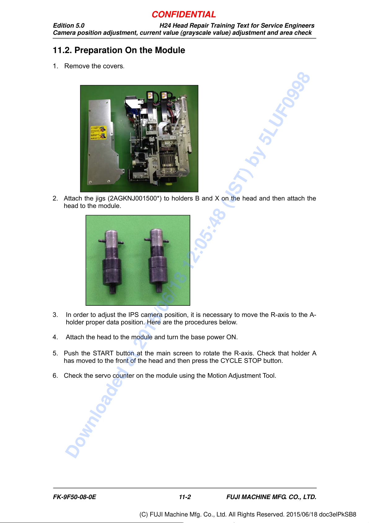
1. Remove the covers.
2. Attach the jigs (2AGKNJ001500*) to holders B and X on the head and then attach the
head to the module.
3. In order to adjust the IPS camera position, it is necessary to move the R-axis to the A-
holder proper data position. Here are the procedures below.
4. Attach the head to the module and turn the base power ON.
5. Push the START button at the main screen to rotate the R-axis. Check that holder A
has moved to the front of the head and then press the CYCLE STOP button.
6. Check the servo counter on the module using the Motion Adjustment Tool.
CONFIDENTIAL
Downloaded at 2015/06/18 12:05:48 (JST) by 5LUF0998
(C) FUJI Machine Mfg. Co., Ltd. All Rights Reserved. 2015/06/18 doc3elPkSB8
Edition 5.0 H24 Head Repair Training Text for Service Engineers
Camera position adjustment, current value (grayscale value) adjustment and area check
FK-9F50-08-0E 11-3 FUJI MACHINE MFG. CO., LTD.
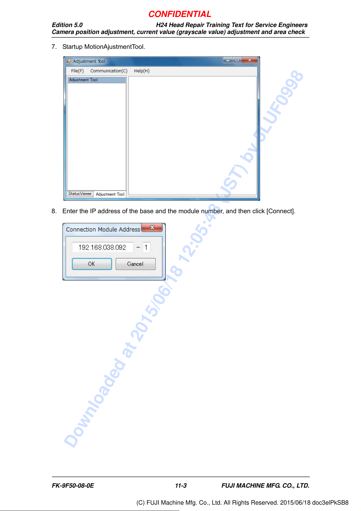
7. Startup MotionAjustmentTool.
8. Enter the IP address of the base and the module number, and then click [Connect].
CONFIDENTIAL
Downloaded at 2015/06/18 12:05:48 (JST) by 5LUF0998
(C) FUJI Machine Mfg. Co., Ltd. All Rights Reserved. 2015/06/18 doc3elPkSB8
Edition 5.0 H24 Head Repair Training Text for Service Engineers
Camera position adjustment, current value (grayscale value) adjustment and area check
FK-9F50-08-0E 11-4 FUJI MACHINE MFG. CO., LTD.
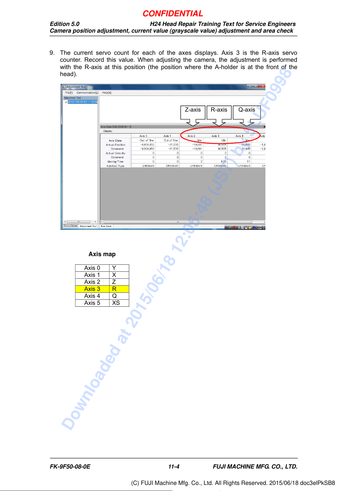
9. The current servo count for each of the axes displays. Axis 3 is the R-axis servo
counter. Record this value. When adjusting the camera, the adjustment is performed
with the R-axis at this position (the position where the A-holder is at the front of the
head).
Axis map
Axis 0
Y
Axis 1 X
Axis 2 Z
Axis 3 R
Axis 4 Q
Axis 5 XS
Z-axis R-axis Q-axis
CONFIDENTIAL
Downloaded at 2015/06/18 12:05:48 (JST) by 5LUF0998
(C) FUJI Machine Mfg. Co., Ltd. All Rights Reserved. 2015/06/18 doc3elPkSB8