1_H24维修手册.pdf - 第146页
Edition 5.0 H24 Head Re pair T raining T ext for Ser v ice Enginee rs Camer a posi t ion adjus t ment, curr ent value (gr ays cale value ) a djustmen t a nd area ch ec k FK -9F50- 08-0E 1 1 -6 FU JI MACHINE MFG . CO., L …
Edition 5.0 H24 Head Repair Training Text for Service Engineers
Camera position adjustment, current value (grayscale value) adjustment and area check
FK-9F50-08-0E 11-5 FUJI MACHINE MFG. CO., LTD.
10. Close MotionAjustmentTool.
11. Press the POWER button to set the module to sleep and turn OFF the head power.
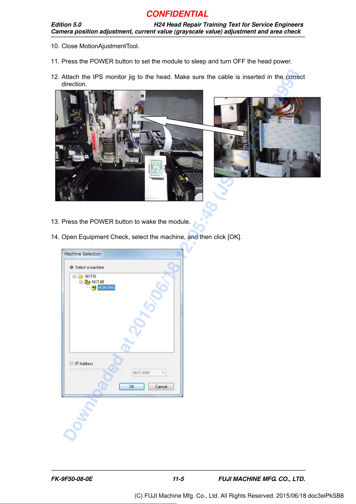
12. Attach the IPS monitor jig to the head. Make sure the cable is inserted in the correct
direction.
13. Press the POWER button to wake the module.
14. Open Equipment Check, select the machine, and then click [OK].
CONFIDENTIAL
Downloaded at 2015/06/18 12:05:48 (JST) by 5LUF0998
(C) FUJI Machine Mfg. Co., Ltd. All Rights Reserved. 2015/06/18 doc3elPkSB8
Edition 5.0 H24 Head Repair Training Text for Service Engineers
Camera position adjustment, current value (grayscale value) adjustment and area check
FK-9F50-08-0E 11-6 FUJI MACHINE MFG. CO., LTD.
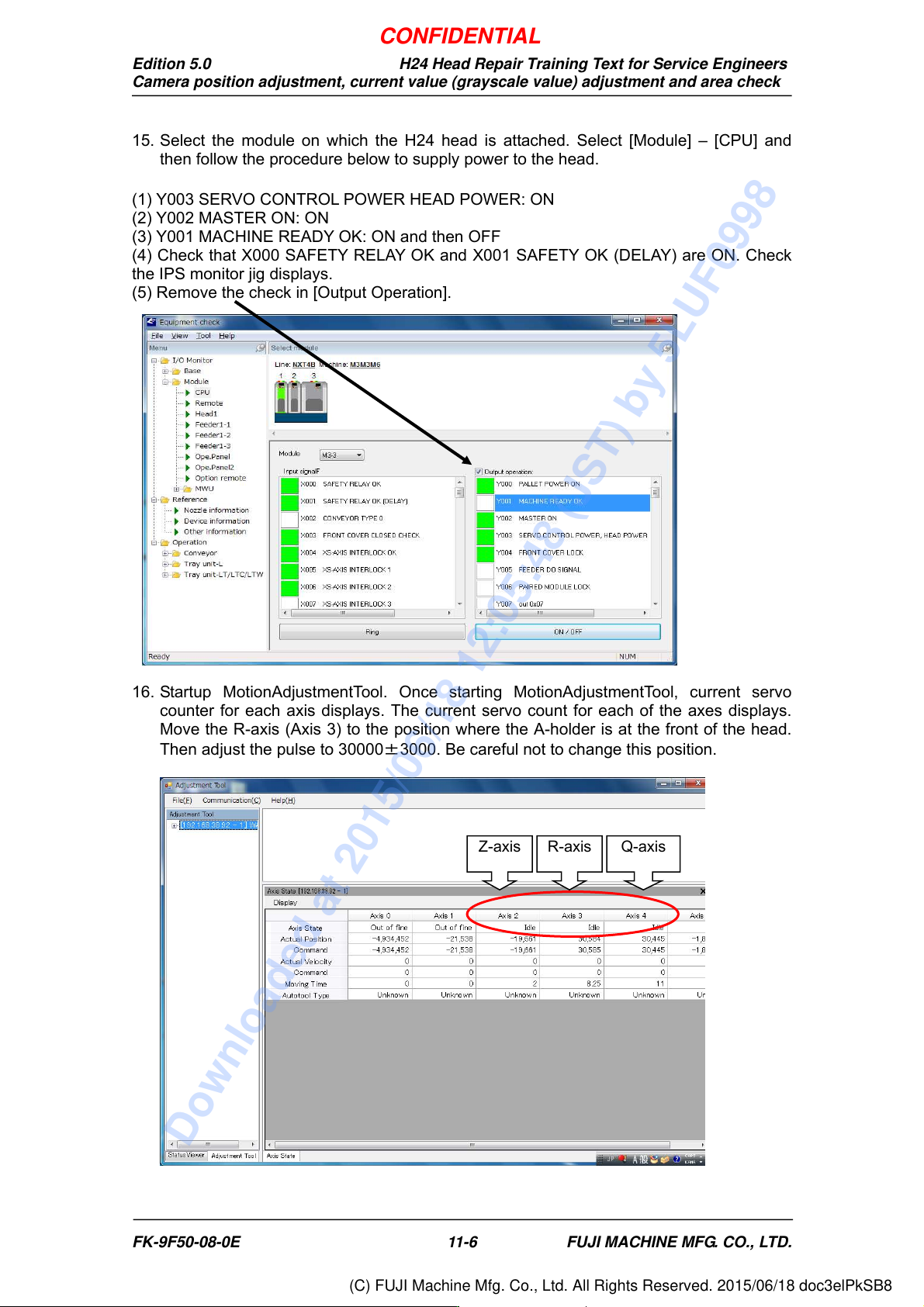
15. Select the module on which the H24 head is attached. Select [Module] – [CPU] and
then follow the procedure below to supply power to the head.
(1) Y003 SERVO CONTROL POWER HEAD POWER: ON
(2) Y002 MASTER ON: ON
(3) Y001 MACHINE READY OK: ON and then OFF
(4) Check that X000 SAFETY RELAY OK and X001 SAFETY OK (DELAY) are ON. Check
the IPS monitor jig displays.
(5) Remove the check in [Output Operation].
16. Startup MotionAdjustmentTool. Once starting MotionAdjustmentTool, current servo
counter for each axis displays. The current servo count for each of the axes displays.
Move the R-axis (Axis 3) to the position where the A-holder is at the front of the head.
Then adjust the pulse to 30000±3000. Be careful not to change this position.
Z-axis R-axis Q-axis
CONFIDENTIAL
Downloaded at 2015/06/18 12:05:48 (JST) by 5LUF0998
(C) FUJI Machine Mfg. Co., Ltd. All Rights Reserved. 2015/06/18 doc3elPkSB8
Edition 5.0 H24 Head Repair Training Text for Service Engineers
Camera position adjustment, current value (grayscale value) adjustment and area check
FK-9F50-08-0E 11-7 FUJI MACHINE MFG. CO., LTD.
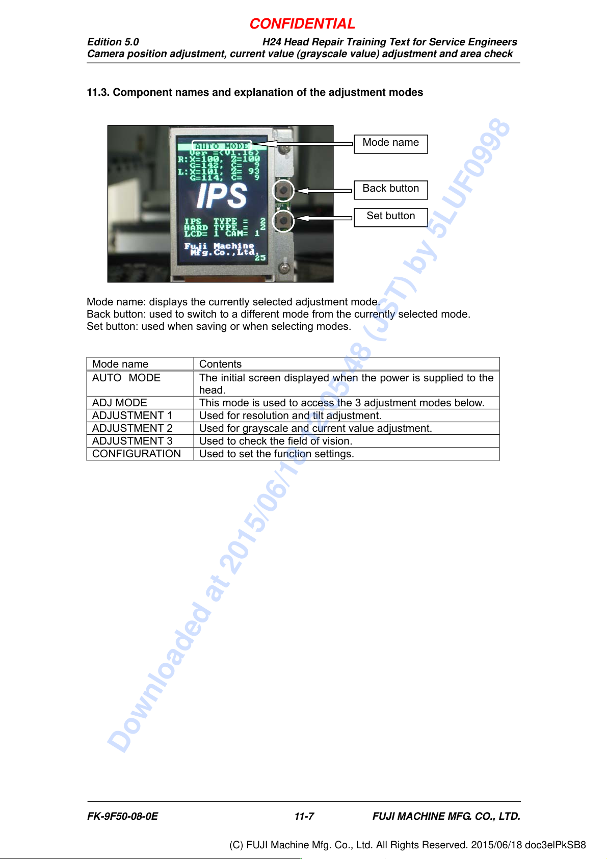
11.3. Component names and explanation of the adjustment modes
Mode name: displays the currently selected adjustment mode.
Back button: used to switch to a different mode from the currently selected mode.
Set button: used when saving or when selecting modes.
Mode name Contents
AUTO MODE The initial screen displayed when the power is supplied to the
head.
ADJ MODE This mode is used to access the 3 adjustment modes below.
ADJUSTMENT 1 Used for resolution and tilt adjustment.
ADJUSTMENT 2 Used for grayscale and current value adjustment.
ADJUSTMENT 3 Used to check the field of vision.
CONFIGURATION Used to set the function settings.
Back button
Set button
Mode name
CONFIDENTIAL
Downloaded at 2015/06/18 12:05:48 (JST) by 5LUF0998
(C) FUJI Machine Mfg. Co., Ltd. All Rights Reserved. 2015/06/18 doc3elPkSB8