1_H24维修手册.pdf - 第178页
E d i ti o n 5 .0 H 24 H ead R ep ai r T r ai n i n g T ext f o r S er vi ce E n g i n ee r s Pr o p e r d at a m e a s u r e m e n t fo r H 2 4 h e a d u s i n g h e a d b e n c h 6. A t t ac h t he Q 0 pr o per dat a m…
Edition 5.0 H24 Head Repair Training Text for Service Engineers
Proper data measurement for H24 head using head bench
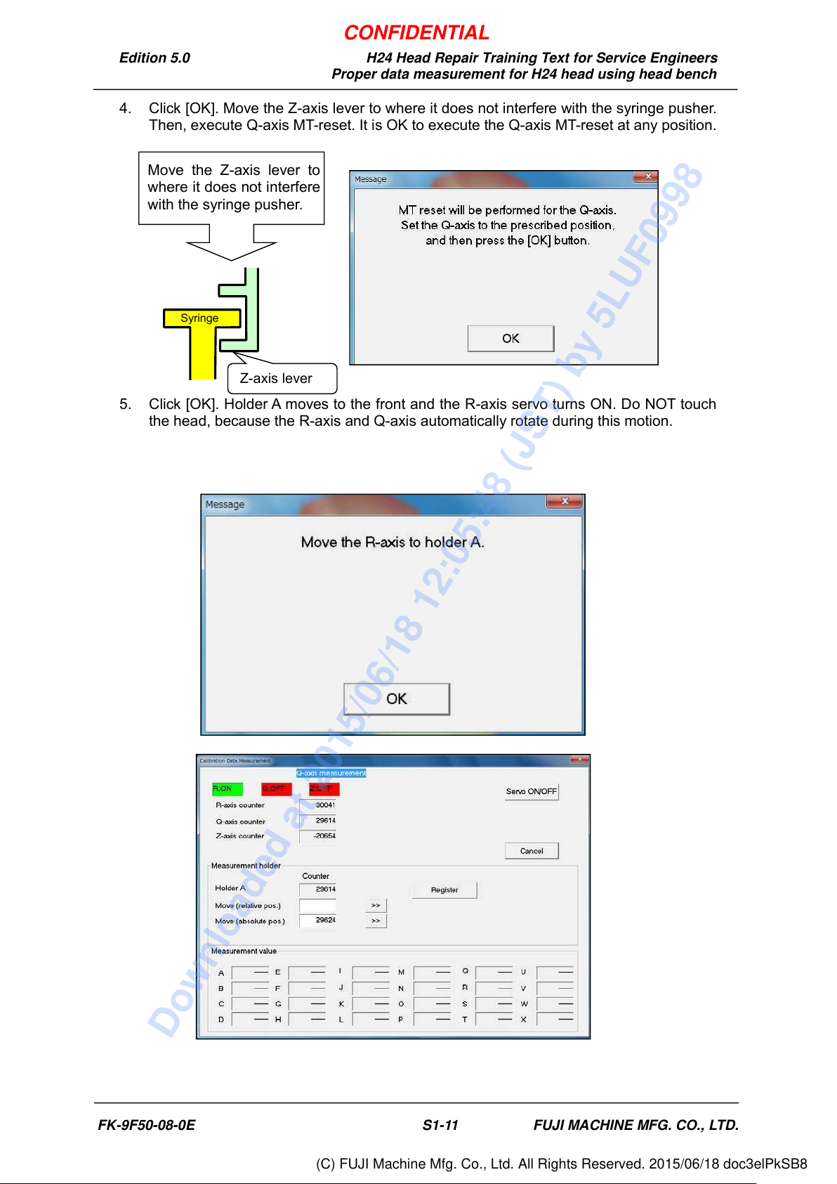
4. Click [OK]. Move the Z-axis lever to where it does not interfere with the syringe pusher.
Then, execute Q-axis MT-reset. It is OK to execute the Q-axis MT-reset at any position.
5. Click [OK]. Holder A moves to the front and the R-axis servo turns ON. Do NOT touch
the head, because the R-axis and Q-axis automatically rotate during this motion.
Move the Z-axis lever to
where it does not interfere
with the syringe pusher.
Z-axis lever
Syringe
FK-9F50-08-0E S1-11 FUJI MACHINE MFG. CO., LTD.
CONFIDENTIAL
Downloaded at 2015/06/18 12:05:48 (JST) by 5LUF0998
(C) FUJI Machine Mfg. Co., Ltd. All Rights Reserved. 2015/06/18 doc3elPkSB8
Edition 5.0 H24 Head Repair Training Text for Service Engineers
Proper data measurement for H24 head using head bench
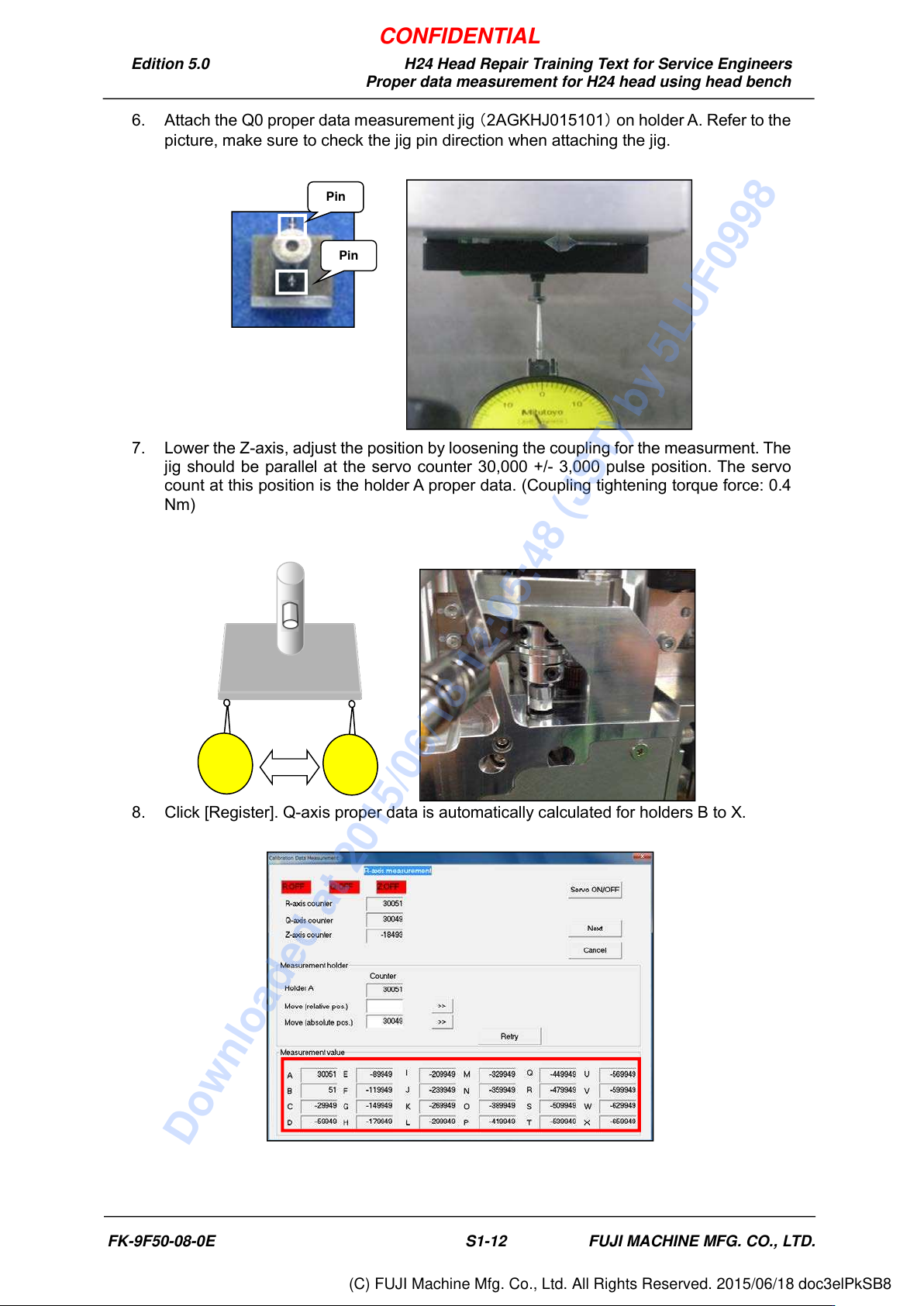
6. Attach the Q0 proper data measurement jig (2AGKHJ015101) on holder A. Refer to the
picture, make sure to check the jig pin direction when attaching the jig.
7. Lower the Z-axis, adjust the position by loosening the coupling for the measurment. The
jig should be parallel at the servo counter 30,000 +/- 3,000 pulse position. The servo
count at this position is the holder A proper data. (Coupling tightening torque force: 0.4
Nm)
8. Click [Register]. Q-axis proper data is automatically calculated for holders B to X.
自動計算さ
れた状態
Pin
Pin
FK-9F50-08-0E S1-12 FUJI MACHINE MFG. CO., LTD.
CONFIDENTIAL
Downloaded at 2015/06/18 12:05:48 (JST) by 5LUF0998
(C) FUJI Machine Mfg. Co., Ltd. All Rights Reserved. 2015/06/18 doc3elPkSB8
Edition 5.0 H24 Head Repair Training Text for Service Engineers
Proper data measurement for H24 head using head bench
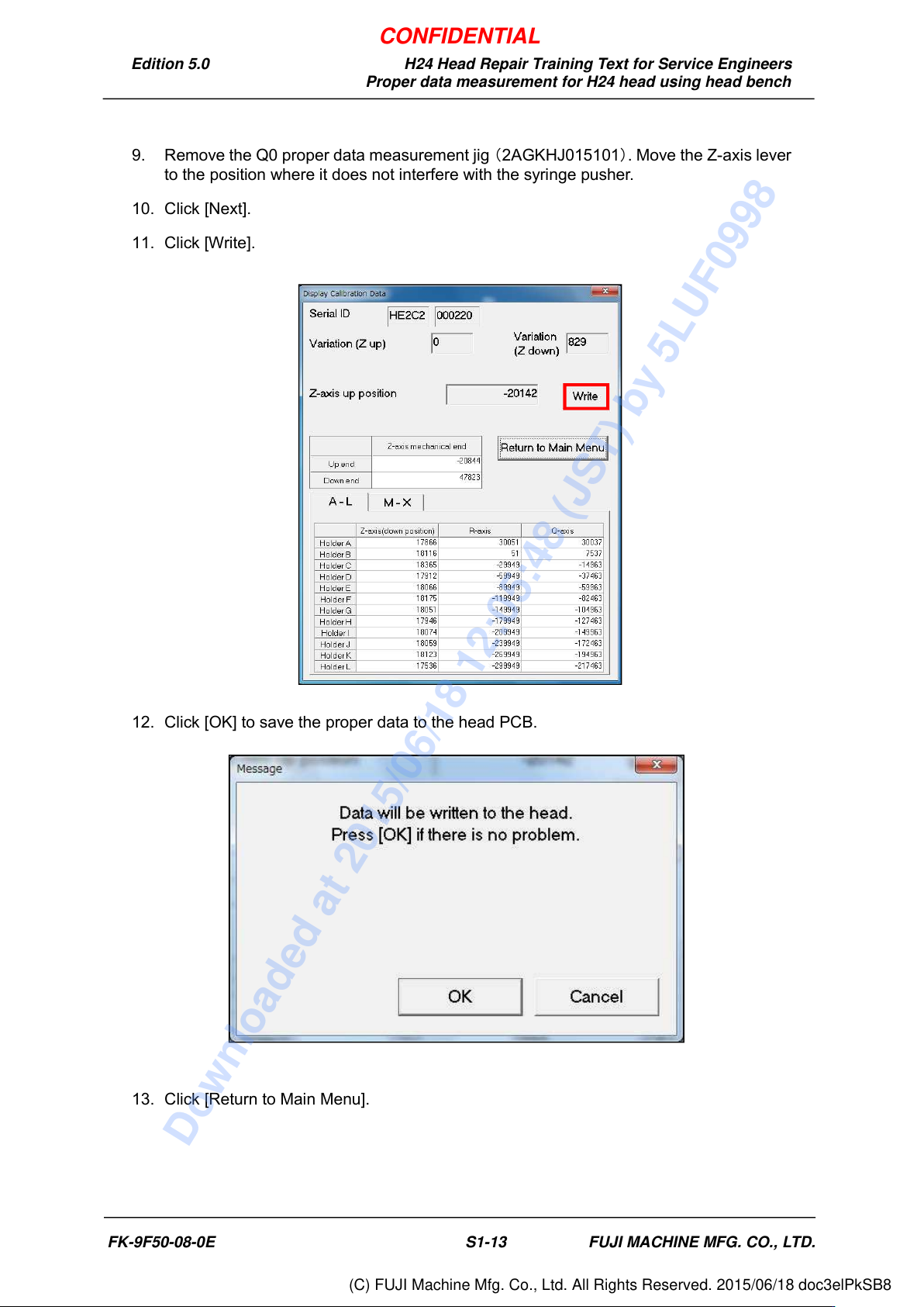
9. Remove the Q0 proper data measurement jig (2AGKHJ015101). Move the Z-axis lever
to the position where it does not interfere with the syringe pusher.
10. Click [Next].
11. Click [Write].
12. Click [OK] to save the proper data to the head PCB.
13. Click [Return to Main Menu].
FK-9F50-08-0E S1-13 FUJI MACHINE MFG. CO., LTD.
CONFIDENTIAL
Downloaded at 2015/06/18 12:05:48 (JST) by 5LUF0998
(C) FUJI Machine Mfg. Co., Ltd. All Rights Reserved. 2015/06/18 doc3elPkSB8